SSZT371 november 2019 CSD95490Q5MC , TPSM831D31 , UCD90320U
Aerospace and defense applications, from ruggedized communications to radar to avionics equipment, require intelligent power with accurate voltage regulation, high power density, high efficiency and comprehensive system diagnostics for high reliability.
More and more aerospace and defense applications are using faster, higher-performance processors and field-programmable gate arrays (FPGAs). As shown in Figure 1, radar requires not just a DC/DC converter for the digital signal processor (DSP), FPGA and input/output (I/O) rails, but also a sequencer to provide accurate sequencing for power-up and power-down scenarios.
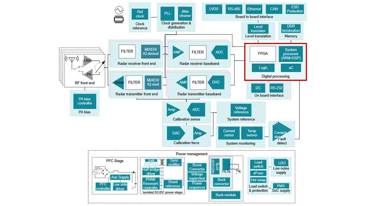 Figure 1 Radar block diagram
Why do you need to sequence the power rails?
Improperly sequenced power rails present several risks to the power supply, including compromised reliability (which can lead to device failures), stress on the integrated circuit, reduced application life and immediate faults, which relate to excessive voltage differentials and current inflow. Figure 2 shows a typical power-sequencing diagram.
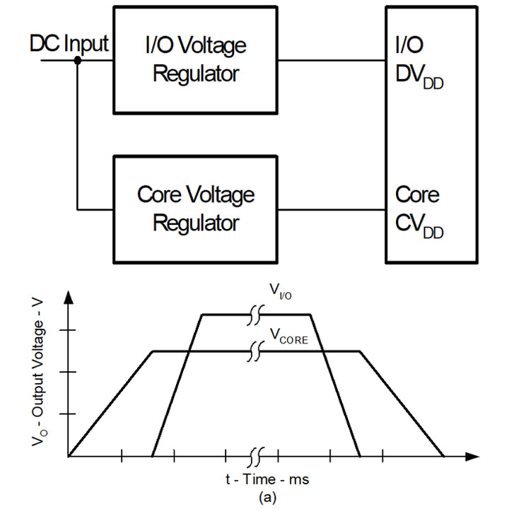 Figure 2 Power-sequencing diagram
As shown in Figure 3, there are three types of sequencing schemes: sequential, ratiometric and simultaneous:
-
Sequential is when two or more voltage rails power up or power down in sequence at different slew rates and with different final values.
-
Ratiometric is when two or more voltage rails power up or power down at the same time at different slew rates and with different final values.
-
Simultaneous is when two or more voltage rails power up or power down at the same time with the same slew rate but different final values.
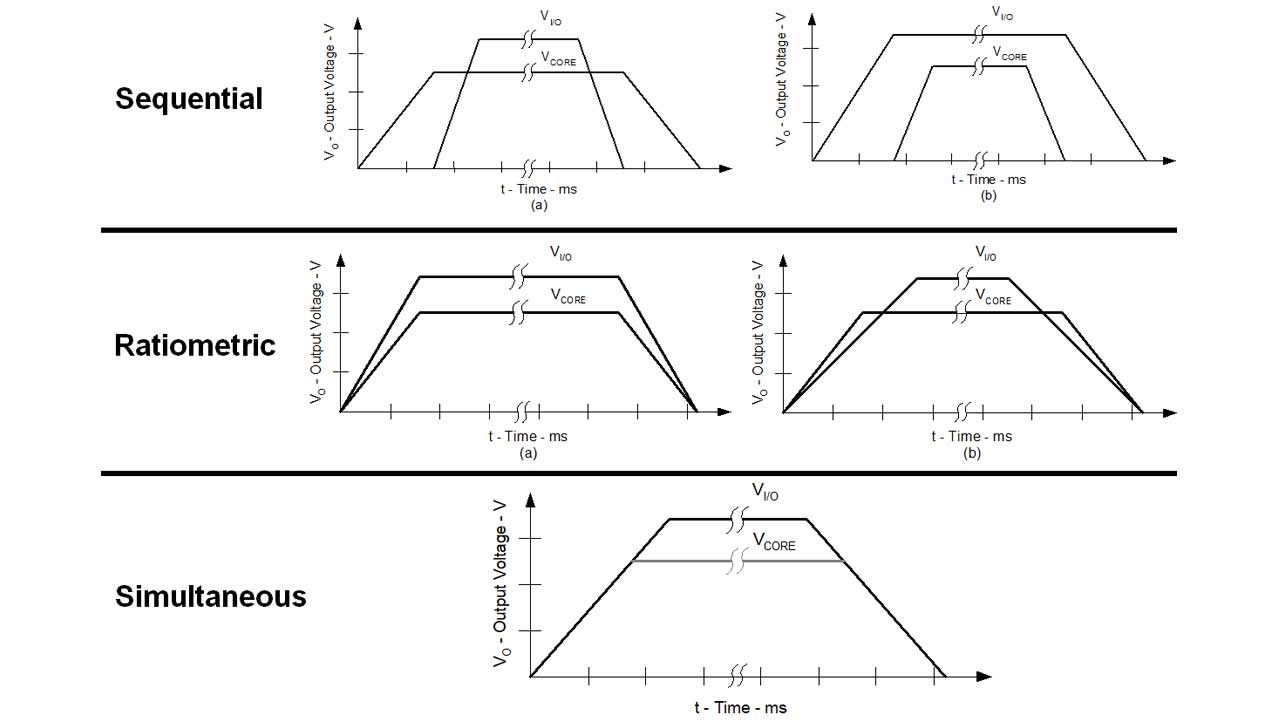 Figure 3 Types of voltage rail sequencing
The ability to address all of these sequencing schemes but also monitor the power-supply rails and report system warnings and faults with flexibility and ease of use is critical in order to prevent runaway issues like overcurrent and overtemperature.
The UCD90320U is TI’s newest 32-channel PMBus sequencer which can be programmed and reconfigured through its onboard nonvolatile memory for a wide range of sequencing scenarios through the Fusion Digital Power™ Designer graphical user interface, as shown in Figure 4.
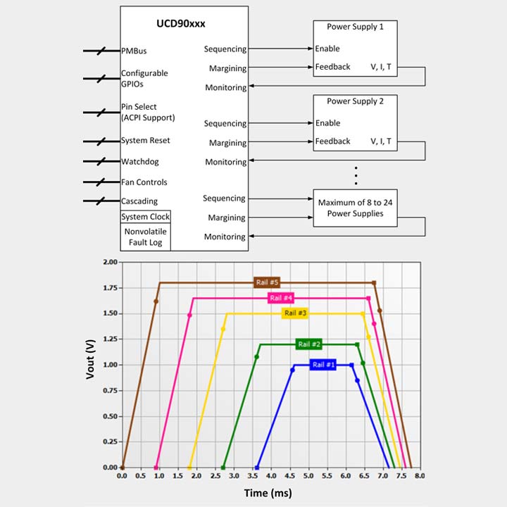 Figure 4 Voltage rail sequence timing configuration window in Fusion Digital Power Designer
Dealing with ionizing radiation exposure
In radar and other defense applications, there may be instances of ionizing radiation exposure. When this happens, the failure-in-time (FIT) rate can increase; that is, the probability of failure can increase. A typical instance of ionizing radiation failures in semiconductors is a single-event upset (SEU). An SEU is caused by ionizing radiation strikes that discharge the charge in storage elements such as configuration memory cells, user memory and registers, resulting in a bit flip as shown in Figure 5. The change caused by an SEU is considered “soft” because the circuit/device itself is not permanently damaged by the radiation. If a new data is written to the bit, the device will store the new data correctly.
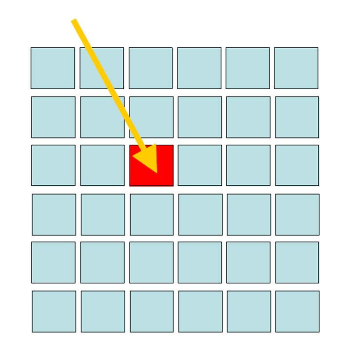 Figure 5 An ionizing radiation SEU affecting a memory cell
In terrestrial applications, the two radiation sources of concern are alpha particles emitted from package impurities and high-energy neutrons caused by the interaction of cosmic rays with the earth’s atmosphere. Studies conducted over the last 20 years have led to high-purity package materials (ultra-low alpha [ULA]), which can minimize SEU effects caused by alpha particle radiation. Unavoidable atmospheric neutrons remain the primary cause of SEU effects today.
The UCD90320U uses a compact 0.8-mm pitch ball-grid array package with a ULA mold compound to reduce the soft errors caused by ionizing alpha particles. This sequencer/monitor also has the ability to scan the user-configuration static random access memory to detect SEUs. Both ULA and SEU detection features provide higher reliability for radar and other defense applications. Based on actual customer results, the FIT rate dropped to 10 with the UCD90320U in the ULA package, versus a FIT rate of 1,344 with the non-ULA package.
Achieving effective voltage regulation
After successfully sequencing the FPGA rails, the FPGA core rail is the most critical in terms of voltage regulation, power density, thermal performance and efficiency. Some of the latest FPGAs require a total tolerance of ±2% DC plus AC (AC = load transient), which makes voltage regulator design challenging. Table 1 lists typical high-current FPGA core and I/O rail design specifications.
| PARAMETER | SPECIFICATIONS |
|---|---|
| Input supply | 12 V, ±5% |
| Switching frequency | 500 kHz |
| Power stages | CSD95490Q5MC |
| Core rail | |
| Nominal output voltage | 0.9 V |
| DC+AC tolerance | ±2% |
| Max output current | 120 A |
| DC load line | - |
| Max load step | 30 A at 100 A/μs |
| Number of phases | 3 |
| COUT, BULK | 12x 470 μF, 2.5 V, 3 mΩ |
| COUT, MLCC | 22x 220 μF, 4 V, X5R |
| I/O rail | |
| Nominal output voltage | 0.9 V |
| DC+AC tolerance | ±2% |
| Max output current | 20 A |
| DC load line | - |
| Max load step | 10 A at 100 A/μs |
| Number of phases | 1 |
| COUT, BULK | 8x 470 μF, 2.5 V, 3 mΩ |
| COUT, MLCC | 8x 220 μF, 4 V, X5R |
Radar and other defense equipment customers typically prefer power modules for the ease of use and maintenance-free benefit. For an FPGA requiring 120 A of output current, an equivalent discrete multiphase buck voltage regulator solution requires 66 discrete components and hundreds of hours of design, layout, lab testing, prototyping, reliability and final testing. The design will also be subjected to electromagnetic compatibility testing, and for defense applications, shock and vibration testing as well.
For the highest-performance FPGA, TI’s TPSM831D31https://e2e.ti.com/controlpanel/blogs/posteditor.aspx/ 120-A plus 40-A dual-output PMBus buck module can help designers meet ±2% DC and AC tolerance specifications at high power densities, with 243 W of output power in 720 mm2 of printed circuit board area.
Employing our proprietary DCAP+™ control mode, the TPSM831D31 can reduce the output capacitor count, including the number of multilayer ceramic capacitors required to maintain output voltage regulation during severe load transients. The TPMS831D31 can power both the FPGA core and I/O rails, as shown in Figure 6.
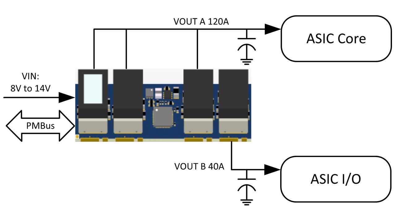 Figure 6 TPSM831D31 application circuit
If you are designing a radar or any other defense equipment using high-current FPGAs and your design priorities are comprehensive sequencing, monitoring, ease of use and high power density for your FPGA DC/DC converter, consider using reconfigurable PMBus sequencers such as the UCD90320U and high-performance modules such as the TPSM831D31.
Additional resources:
- Check out the TI training resources on "How to Use the Fusion Digital Power Designer with UCD90x Sequencers."https://training.ti.com/fusion-digital-power-designer
- Learn more about sequencers in our Sequencers 101 training.
- Read the technical article, "An introduction to the D-CAP+ modulator and its real-world performance."https://e2e.ti.com/blogs_/b/powerhouse/archive/2017/11/08/an-introduction-to-the-d-cap-modulator-and-its-real-world-performance
- See the main features of configuring voltage rails for sequencing in the TI training video, "Fusion Power Designer: Set rail sequencing."