SSZT350 january 2020 TMS320F28384D , TMS320F28384S , TMS320F28386D , TMS320F28386S , TMS320F28388D , TMS320F28388S

It is a familiar scene in labs across the globe: A design engineer is pushing the envelope, seeking to enhance functionality or improve performance. Unfortunately, while digging deep into low-level system timing, a design stalemate occurs. The potential solution demands the alteration of key control signals. These situations can impede creativity, leaving engineers with one wish: “If only there was a way to customize logic and timing within a control peripheral.” That wish is now a reality with the configurable logic block (CLB) for C2000™ microcontrollers (MCUs).
What is the CLB? The CLB integrates an optimized piece of high-speed programmable logic into a real-time microcontroller like a C2000 MCU. It provides intelligent input/output (I/O) routing to key peripherals such as enhanced pulse-width modulators (PWMs), enhanced capture, enhanced quadrature encoder pulse and general-purpose I/O. The result is an intellectual property enhancement offering system-level differentiation.
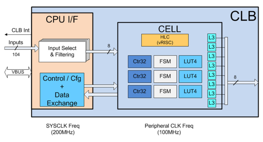
As shown in Figure 1, the CLB tool comprises either two, four or eight tiles. Within each tile is an optimized group of programmable logic cell blocks that contains:
- Three 4-input look-up tables (LUT4).
- Three 32-bit counters (Ctr32).
- Three 4-state finite state machines (FSMs).
- Eight 3-input output look-up tables (L3).
- One high-level controller (HLC).
 Figure 1 Example of CLB tool tile cell
blocks
Figure 1 Example of CLB tool tile cell
blocksBy individually configuring and wiring these cell blocks together, you can generate a custom logic scheme, providing novel solutions to difficult system problems like programming application-specific logic for trip zones, enhancing soft-switching PWM schemes or implementing condition-based quadrature encoder position capture.
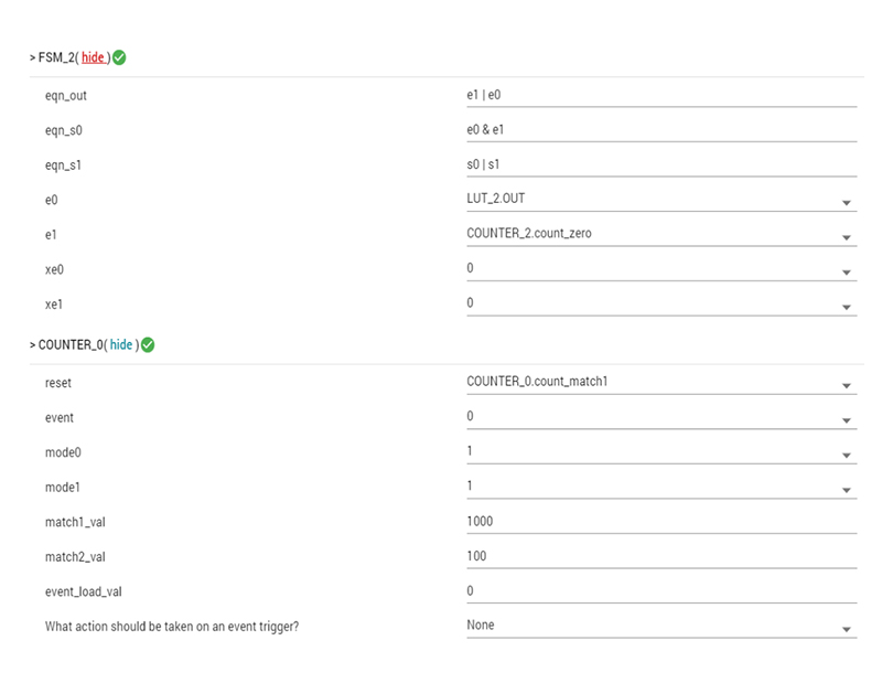
To make development easy, TI created a graphical CLB configuration tool (shown in Figure 2) that is integrated directly into TI’s Code Composer Studio™ integrated development environment for code development and debugging.
 Figure 2 CLB tool graphical
configuration view
Figure 2 CLB tool graphical
configuration viewOnce configured, the generation of the CLB tool output logic is automatic. The project build output is a *.h header file describing the CLB tool configuration. During run-time initialization, the header file descriptors configure the tiles using C2000Ware DriverLib application programming interfaces.
Design engineers are making use of the CLB tool and exploring new areas of product differentiation. Matt Parnell Sr., principal hardware engineer for lifestyle audio at Harman International, has been using the CLB to enhance products.
According to Matt, they are always looking to “bend the limits of engineering.”
“For example, we can now offload custom control logic and diagnostics from the main software control loop to the CLB. At 400 kHz, every cycle counts, so this reduction in overhead is extremely welcome. These cycle savings open up bandwidth that can be directly applied to more innovative control features,” Matt said.
He also shared how the signal integration of the enhanced PWM (ePWM) peripheral is “profound.”
“Within the CLB, designers can intercept internal ePWM signals such as action qualifiers and dead band, condition with logic, and basically create their own version of a submodule. This feature has already saved the day here at Harman. The CLB adds an incredible amount of customization to an already extremely capable device.”
The new CLB peripheral is breaking barriers in control-oriented design, offering a novel tool set for crafting differentiated solutions. The latest C2000Ware revision includes 15 CLB examples; encoder examples are in the MotorControl sofware development kit. Check out the training and application notes . See how the CLB can defy conventional logic.