SSZT306 may 2020 TMCS1100
Power-factor correction (PFC) and inverters in telecom rectifiers and server power-supply units (PSUs) need to be able to sense the current signal from the high-voltage side for the controller at the low-voltage side. To do so, they use an isolated current sensor. There are many choices for isolated current sensing like current transformers (CTs), isolated amplifiers and Hall-effect current sensors. The Hall-effect current sensor is preferable because it is simple to use, accurate, comes in a small package and has DC capability.
Current transformers are based on the transformer principle and can test the switching on current flow through a metal-oxide semiconductor field-effect transistor (MOSFET)/isolated gate bipolar transistor (IGBT). The CT’s good response time makes it a popular choice for peak current control and overcurrent protection. However, CT’s cannot sense DC or very low frequency current due to their transformer coupling, which results in an accuracy loss (due to the absence of switching-off current) when sensing the AC line current. Reducing the CT’s size is not easy, since it needs a ferrite core. In addition, large CTs could result in increased power loops and switching noise, even a voltage spike.
An accurate, size-efficient alternative, Hall-effect current sensors use magnetic field sensing, which can operate in DC conditions. They can recreate both switching-on and switching-off currents with good linearity and accuracy. The packaging for a Hall-effect sensor, which can be as little as small outline integrated circuit (SOIC)-8, makes printed circuit board (PCB) layout easier, and helps achieve higher power density.
Table 1 compares Hall-effect current sensors and current transformers.
| Hall-effect current sensors | Current transformers | |
|---|---|---|
| Principle | Hall effect (magnetic field measure) | Transformer (flux coupling) |
| Capability | DC and AC | AC only |
| Size | Smallest: SOIC-8 (5 mm by 6 mm by 1.8 mm) | Smallest: EE5 (7.7 mm by 6.9 mm by 5.4 mm) |
| Accuracy | High – to 1% | Low – depends on many factors |
| Applications | DC/AC current measurement, PFC current control, inverter current control | Peak current control, overcurrent protection |
When using Hall-effect current sensors in telecom power or server PSUs, you need to evaluate the measurable current-sensing ranges, continuous-current capabilities, transient response/bandwidth and isolation voltages. In addition, monitoring power consumption during the PSU’s operation might be a consideration in certain cases. A precision isolated current sensor such as TI’s TMCS1100 can help in scenarios when the AC current measurement will require a degree of accuracy of at least 1%.
| The precision isolated current sensor you need | |

|
Download the TMCS1100 data sheet. |
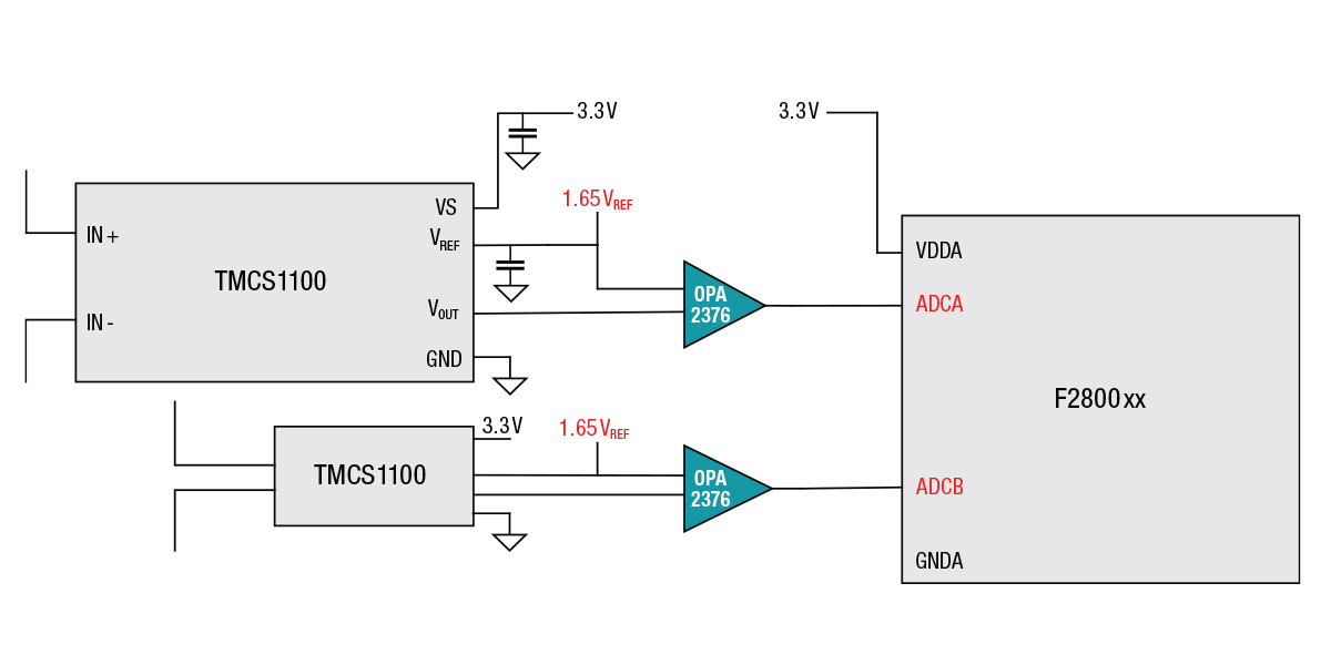
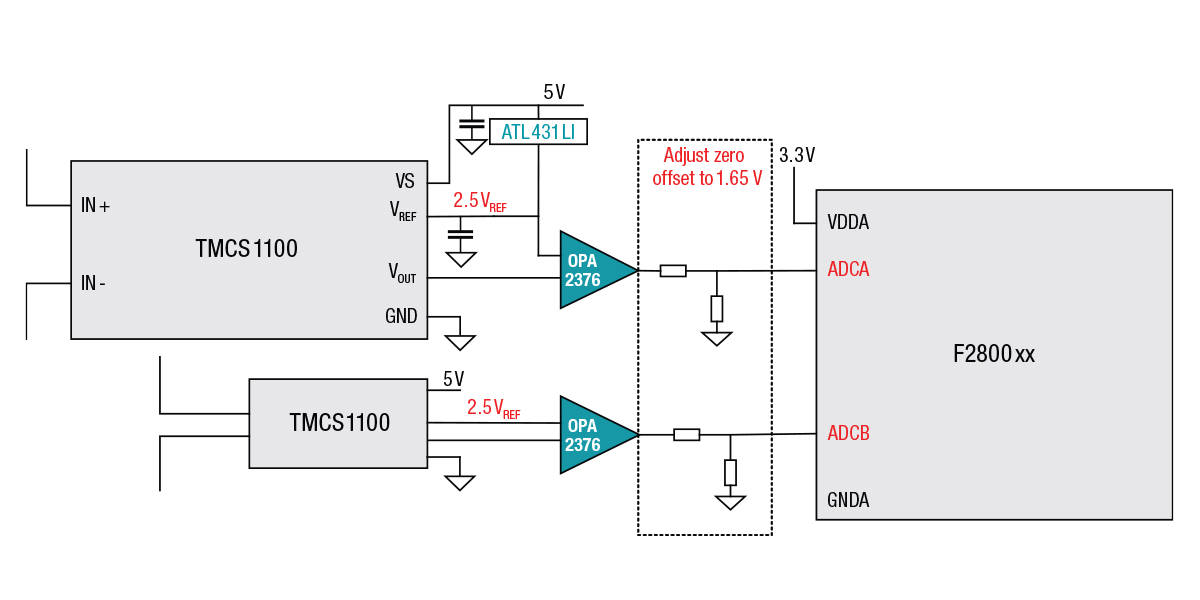
Figure 1 shows the typical application circuits of a Hall-effect current sensor at 3.3 V and at 5 V. Compared to a 3.3-V power supply, using a 5-V power supply, the measurable range could be larger. Take the TMCS1100A1, for example. Its sensitivity is 50 mV/A. If using a 3.3-V power supply, its measurable current is -33 A~ + 33 A bidirectional. When using a 5.0-V power supply, its measurable current could extend to -50 A~ + 50 A. (Besides the measurable range, consider the continuous current range at the same time, which should be enlarged by better thermal dissipation.)

(b)
 Figure 1 A common application of
Hall-effect current sensors: 3.3 V powering the Hall-effect current sensor (a);
5 V powering the Hall-effect current sensor (b)
Figure 1 A common application of
Hall-effect current sensors: 3.3 V powering the Hall-effect current sensor (a);
5 V powering the Hall-effect current sensor (b)The following factors are crucial during Hall-effect current sensor layout:
- Thermal dissipation: maximizing the copper planes for the input current path could increase the current-handling capability of a surface-mounted device Hall-effect sensor integrated circuit. You could potentially use a heavier copper PCB construction, place thermal via farms around the isolated current input, or put the Hall-effect sensor and PCB trace in the airflow.
- Primary current magnetic fields: your layout should minimize adjacent high-current traces in close proximity to the device.
- Isolation requirements: consider the creepage and clearance for system-level isolation requirements. Add additional slots or grooves to the board if you cannot maintain the required PCB creepage between the two sides at the board level.
In telecom rectifiers and server PSUs, a CT is a good fit for peak current control and overcurrent protection, but it is large in size and not very accurate. Hall-effect current sensors are small in size, highly accurate, easy to use in circuit designs, and are more suitable for AC line current sensing.
Additional resources
- Download the TMCS1100 data sheet.
- Read these application notes:
- Check out the TMCS1100EVM user’s guide.