SSZT300 may 2020 CC1310 , CC1350 , SN74AVC4T245 , TM4C1294NCPDT , TPD4E004 , TPD6E004 , TPS796
The evolution of the power grid necessitates the addition of wireless connectivity to existing wired connectivity for asset monitoring and control. The primary contributing factors for adding wireless connectivity include:
- Adoption of decentralized microgrid model with distributed energy resources along with conventional generation, transmission and distribution.
- The heightened need for health and status monitoring of remote power distribution and automation assets supervising the primary equipment to optimize power management; resource allocation; and fault location, isolation and service restoration (FLISR). Remote monitoring of the electrical network helps enable efficient operation of the power grid, reducing number of power outages and power outage time minimizing losses.
Data analytics of grid assets can help operators quickly identify faults while also enabling predictive maintenance for primary equipment, which is nearly nonexistent today. Deciding which specific wireless technology to employ, such as Sub-1 GHz, Bluetooth® Low Energy, Wi-Fi® or multi-standard protocols depends on factors such as data, bandwidth, distance between nodes, the number of connections needed, available power and the required response time.
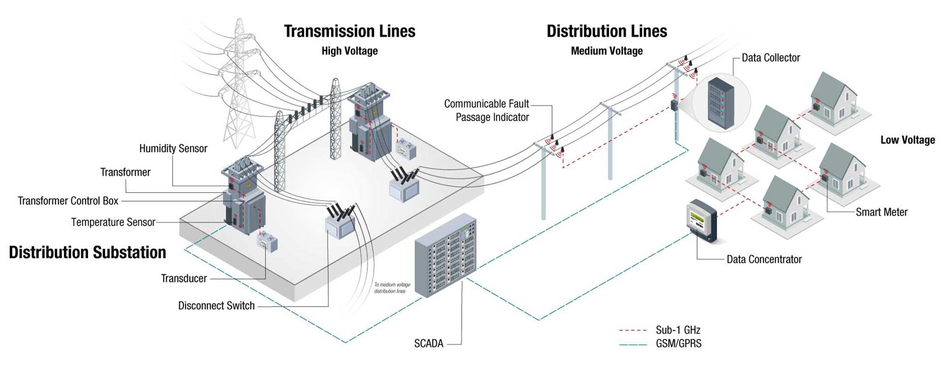
In power grid assets like a fault indicator nodes located in remote locations need to connect to a data collector, as shown in Figure 1 for automatic data exchange with a centralized system. Wireless communication such as Sub-1 GHz is chosen for such an application because it covers a long range (tens of meters to kilometers) and consumes very low power (tens of microamperes of average current). Sub-1 GHz is also a simple to configure, low-cost per node technology when adding multiple nodes in the field for obtaining data on demand from remote equipment using a common collector.
 Figure 1 Using Sub-1 GHz to connect
fault indicators to a data collector
Figure 1 Using Sub-1 GHz to connect
fault indicators to a data collectorAdding Sub-1 GHz connectivity involves two-way communication with a data collector in a star network. The nodes are configured to have faster response time to communicate fault information including location with minimum latency providing faster restoration or self-healing capability.
Sub-1 GHz offers these advantages compared to other wireless connectivity solutions including 2.4-GHz Bluetooth Low Energy communication:
- Longer communication range due to use of lower transmission frequency and data rates since receiver sensitivity is a function of data rate. As a general rule of thumb, reducing data rate by a factor of four can double the communication range.
- Low-frequency (longer wavelength) radio frequency (RF) waves are capable of penetrating through obstacles, which make sub-1 work under multiple environments.
- The low duty cycle allowed in Sub-1 GHz RF regulations results in reduced disturbances.
One of the common grid end equipment using Sub-1 GHz connectivity is the fault current indicator (FCI) used for medium voltage transmission. FCIs are powered by harvesting power from load current. Available current for harvesting is in the range of tens of microamperes. The biggest challenge in integrating connectivity to FCI is its ability to work when load current for harvesting power is not available. Also the requirement for operation over a wide environmental conditions (e.g., line of sight, with obstruction, etc.) inhibits the use a conventional capacitor or certain batteries. Thus, it is critical for RF communication to streamline data transmission to reduce current consumption, which is achieved by optimizing the communication mode between the nodes and the collector.
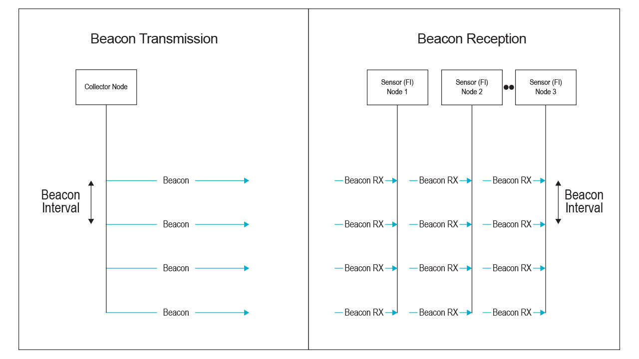
There are two types of modes for managing data transmit (TX) and receive (RX): beacon mode and non-beacon mode. In non-beacon mode, the sensor node is always in receiving mode because there is no defined time when the data collector can communicate with it, which translates to higher current consumption (observed to be ~5 mA). Along with optimized transmit power levels based on the distance between nodes, beacon mode communication (Figure 2) fits best, as it enables duty cycling between wake and sleep modes on the sensor node to help conserve power when the transceiver is off.

 Figure 2 Beacon mode
communication
Figure 2 Beacon mode
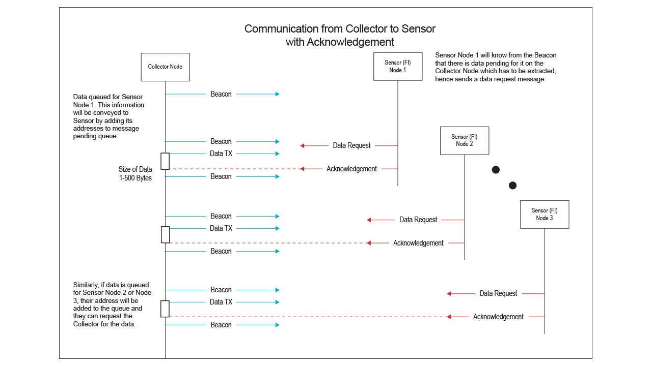
communicationBeacon mode involves broadcasting a beacon from the data collector at a fixed time interval that all of the sensor nodes receive. It synchronizes communication between individual sensor nodes and the collector. Sensor nodes will only wake up to receive beacons, and the deciphering beacon will give information to a sensor if the collector wants to transmit or receive data before the next beacon. This process enables the sensor to switch to sleep mode in the interim, making it ideal for fault indicators.
TI reference design for adding connectivity to FCI
There are a number of hardware and firmware challenges designers encounter when integrating Sub-1 GHz connectivity to FCIs. Our Grid IoT Reference Design: Connecting Fault Indicators, Data Collector, Mini-RTU Using Sub-1 GHz RF showcases:
- The integration of low-power RF, which involves:
- Network setup.
- Using beacon mode for transmission and reception.
- Data exchange including configuration and over-the-air firmware upgrade.
- Fault identification and data communication.
- How to minimize power consumption between fault indicators and the data collector, with:
- Current consumption data provided for the U.S. (915-MHz), European Telecommunications Standards Institute (868-MHz) and China (433-MHz) frequency bands.
- RX current below 6 mA and TX current below 16 mA (at +10 dBm).
- The ability to achieve average current consumption of less than 20 μA for a 5-s beacon interval (a fault indicator configured in RX mode) in a star network.
The reference design helps address the challenges associated with the firmware development for the nodes by using TI’s SimpleLink™ Sub-1 GHz devices for connecting multiple nodes over short distances and the 15.4-stack built on the SimpleLink microcontroller platform, which offers a single development environment with code portability to multiple connectivity protocols and is a ready-to-use, easy-to-update solution for connecting low-power sensors.
Sub-1 GHz is a simple, easy-to-use-and-install, cost optimized approach to add wireless connectivity to existing grid assets, making the legacy assets more reliable and providing faster fault response.
Are you working on grid connectivity in any form? What challenges are you facing? Tell us in the comments.