SSZT218 december 2020 BQ75614-Q1 , BQ79600-Q1 , BQ79612-Q1 , BQ79614-Q1 , BQ79616-Q1 , BQ79656-Q1
As more vehicles become electrified, the need to achieve the highest levels of functional safety with high-accuracy battery monitoring is paramount. Yet in order to improve battery-monitoring accuracy, the vehicle’s battery management system must work efficiently in real time to monitor the performance of the individual battery cells within.
In typical hybrid electric vehicle (HEV) and electric vehicle (EV) configurations, the battery management unit (BMU) is powered from a 12-V battery. This battery remains on even when the car is parked or turned off, in order to support features like remote key entry, security and battery monitoring. When the car is parked, to ensure proper health of the battery, the microcontroller (MCU) has to periodically wake up to look for faults in high-voltage battery packs. This periodic wakeup draws current and can prematurely discharge the 12-V battery.
Design engineers and automotive manufacturers can now consider a new automatic host reverse wake-up feature that enables the host MCU to be off and rely instead on a supply power-management integrated circuit (PMIC) to remain in low-power mode and conserve 12-V battery power.
Examining a wake-up-at-fault battery design
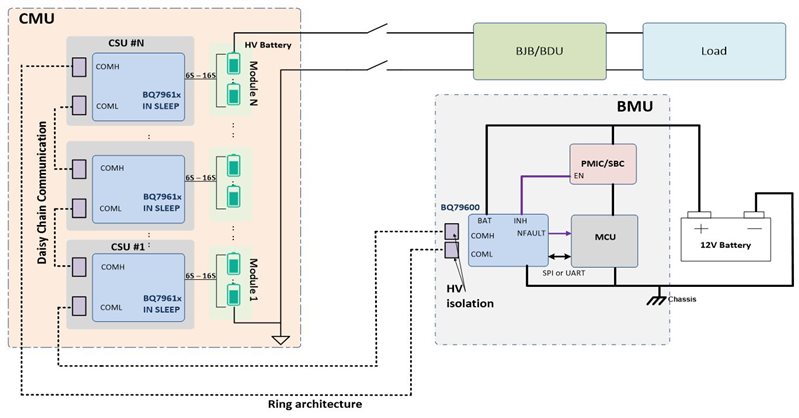
As illustrated in Figure 1, EV battery packs can stack up to 800 V and beyond to support the demanding loads of the AC motor. These battery packs comprise hundreds of cells stacked together in series. A distributed battery pack system supports high-cell-count packs by connecting multiple high-accuracy battery monitors on separate printed circuit boards called cell sensing units.
The BMU board holds the host MCU, its supply (a PMIC or system-basis chip [SBC]) and a communication interface, which links the MCU and battery-monitoring devices on the cell monitoring unit, which then connects to the actual battery cells. A ring connection is supported to reverse the daisy-chain communication direction in the event of cable failure. The host MCU interfaces with the control unit of the vehicle through a Controller Area Network bus. By effectively monitoring each battery cell, an EV’s MCU can ensure the proper operation of all battery cells.
 Figure 1 Simplified battery management system diagram
Improving accuracy with TI’s battery monitors and balancers
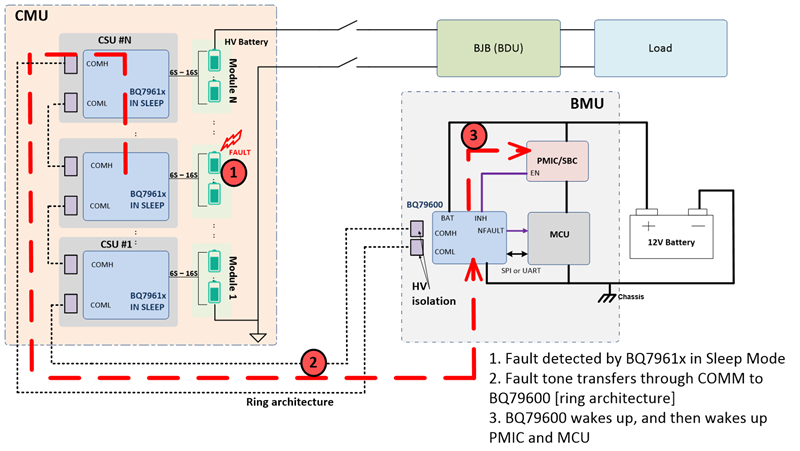
TI’s BQ79616-Q1 battery monitor and balancer can continuously monitor the high-voltage battery even in sleep mode. In case of a fault in the battery, the BQ79616-Q1 transfers the fault information through the daisy-chain configuration to the BQ79600-Q1 communication interface. In turn, the BQ79600-Q1 wakes up and commands the PMIC and MCU to wake up. The MCU does not have to periodically wake up on its own, and can instead rely on the BQ79616-Q1 monitor. Thus, the BQ79600-Q1 – along with the BQ79616-Q1 automatic host reverse wake-up feature – allows the MCU to be off and its PMIC to be in lower-power mode, which minimizes current draw on the 12-V battery and conserves battery power.
As illustrated in Figure 2, when the BQ79616-Q1 is in sleep mode, the low-power operation mode, cell overtemperature and undertemperature, cell overvoltage and undervoltage, and thermistor overtemperature and undertemperature fault detections are still active. Because communication is not available in sleep mode, the device provides an option to transmit the fault status through heartbeat (device in no fault state) and fault (device in fault state) tones.
These tones are transmitted in the same direction as a communication command frame. Unlike communication tones, heartbeat and fault tones are transmitted periodically. The heartbeat and fault tone receivers are always on in sleep mode. For the tone signal to return back to the base device (in order to trigger NFAULT), a ring architecture is necessary to support transmitting fault status in sleep mode. Once the BQ79600-Q1 sniffer detects a fault tone, it puts itself into validate mode to check if a true fault exists or not. If a true fault exists, the BQ79600-Q1 triggers the INH pin, a high-voltage output pin that provides voltage to enable the PMIC.
 Figure 2 Automatic host reverse wakeup with TI battery monitors and balancers
Conclusion
The BQ79616-Q1 family of battery monitors and balancers supports automatic host reverse wakeup, which enables the host MCU to remain off and its power supply to be in the lowest-power mode while the BQ79600-Q1 monitors for faults coming from stacked battery-monitoring devices. The BQ79600-Q1 wakes up the SBC through the INH pin, which then further wakes up the MCU if the event of an unmasked fault detected by the BQ79600-Q1 or stacked BQ79616-Q1s. This enables the conservation of 12-V battery power and supports functional safety requirements like cell monitoring for overvoltage, undervoltage, overtemperature, undertemperature, thermistor overtemperature and thermistor undertemperature, even when the EV is parked or turned off.