SSZT194 february 2021 INA240-SEP , INA901-SP
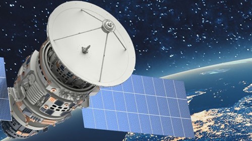
Several commercial satellite companies have entered the space sector with a major impact, revolutionizing this once largely government-funded activity. The need to launch more satellites per year is driven by companies wanting to develop telecommunications mega-constellations, robust radar networks and enhanced optical imaging platforms into low-Earth orbit, medium-Earth orbit and geostationary equatorial orbit. These missions have led designers to pivot from basing satellite designs on simple discrete components such as op-amps or transistors in favor of using more highly integrated circuits, which helps save time with design effort, assembly, and test.
Current-sense amplifiers (CSAs) are a good fit in a wide variety of applications throughout a satellite’s electronic systems. In this article, I’ll discuss how CSAs can monitor the health and functionality for satellite power distribution systems and electrical motors by implementing features such as power-rail current monitoring, point-of-load detection and motor-drive control.
Satellite current monitoring
One of the most common use cases for CSAs in a satellite is to monitor the main power-rail input current to detect single-event transients. Because a CSA can handle the application of voltages greater than the supply voltage to its input pins, it offers more design flexibility than traditional operational amplifiers or other discrete solutions, where the common-mode input pin voltage is bound by the supply voltages of the amplifier.
A CSA enables both high- and low-side sensing designs; you can configure your system to have a shunt resistor before or after the load, and can monitor for anomalies in the expected delivered load current such as an overcurrent event. Table 1 summarizes the trade-offs of high- and low-side implementations.
| High side | Low side | |
|---|---|---|
| Implementation | Differential input | Single or differential input |
| Ground disturbance | No | Yes |
| Common voltage | Close to supply | Close to ground |
| Common-mode rejection ratio requirements | Higher | Lower |
| Load short detection | Yes | No |
Our QML Class V space-grade CSA, the INA901-SP, is capable of both high- and low-side sensing, with an input voltage ranging from –15 V to 65 V, a 50-krad(Si) radiation-hardened-assured (RHA) specification at a low dose rate and single-event latch up (SEL) immunity characterized up to an LETEFF = 75 MeV-cm2/mg SEL. The INA901-SP helps minimize the number of devices required to monitor supply-rail health and protect satellite systems from an overcurrent event.
Point-of-load detection
Leveraging a CSA for point-of-load detection is useful to collect data on vital system components to determine the health or power consumption of particular system loads. Using data from the CSA, the system can make data-driven decisions such as self-calibration or throttling load components to ensure proper operation outside normal operations. A CSA’s accuracy, high voltage range and supply voltage-independent common-mode range make it possible to more easily monitor mission-critical components and help ensure mission success.
Motor-drive applications
In motor-drive applications, the motor-driver circuitry generates pulse-width modulated (PWM) signals to precisely control a motor’s operation. These modulated signals are subject to the monitoring circuitry placed in line with each motor phase, which delivers feedback information for the control circuit. Because real-world amplifiers as opposed to theoretical amplifiers are less than perfect, the output can be affected by the failure of the amplifier to adequately reject the large PWM-driven input voltage steps of the common-mode voltage. Real-world amplifiers do not have infinite common-mode rejection, and undesirable fluctuations appear at the amplifier output corresponding to each input voltage step. Figure 1 shows the outputs of a competing device, while Figure 2 shows the INA240-SEP output.
 Figure 1 Competitor output vs. PWM
input
Figure 1 Competitor output vs. PWM
input Figure 2 INA240-SEP output vs. PWM
input
Figure 2 INA240-SEP output vs. PWM
inputThese output fluctuations can be fairly large, and depending on the characteristics of the amplifier, can take significant time to settle following the input transition. Leveraging the enhanced PWM rejection technology in the INA240-SEP helps provide high levels of suppression for large common-mode transients (ΔV/Δt) in systems that use PWM signals, which is especially useful in motor-drive and solenoid applications. This feature enables accurate current measurements with reduced transients and associated recovery ripple on the output voltage.
The INA240-SEP is an ultra-precise device packaged in space-enhanced plastic that is capable of –4-V to 80-V common-mode voltage with gain error of 0.2%; a gain drift of 2.5 ppm/°C; and an offset voltage of ±25 μV, which is part of TI’s radiation tolerant portfolio know as “Space Enhanced Plastic” (Space EP) to 30-krad(Si) RHA with SEL immunity up to 43 MeV-cm2/mg at 125°C, targeting low earth orbit applications.
Conclusion
Current sensing provides many benefits to a system, including optimized performance, improved reliability and condition monitoring to protect system vitals. Because space-grade CSAs enable direct measurements with highly accurate results, they help systems perform correctly for many years in the harshest environments.
Additional Resources
- Learn more about the TI Space Products guide
- Learn more about TI's portfolio of current-sense amplifiers