SSZT191 february 2021 BQ769142 , BQ76942 , BQ76952 , BQ76972 , ISO1640
As we begin to see battery technology in more applications, new challenges arise. Many applications in the industrial space require higher cell counts than battery-powered applications such as cellphones and laptops. Industrial battery-management systems such as e-mobility, battery-backup units and vacuum cleaners can feature 12, 16, 24 or even more battery cells in series. Traditional battery monitors can only support 16 cells in series per device, which means that battery-management systems with more than 16 cells in series will require multiple battery monitor devices. Stacking multiple monitors will require extra components so that the monitors within the system can communicate with one another.
Stacking with TI’s BQ76952
The BQ76952 monitors the battery pack for several types of system faults. When one of these faults occur, the fault signal needs to be communicated to the protection field-effect transistors (FETs). All battery monitors in the stack need to connect to these FETs. The BQ76952 features high-side N-channel FET drivers, which are less practical to use in a stacked configuration. Instead, combining the protection signals at ground level will help control the low-side protection FETs.
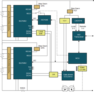
Figure 1 shows a block diagram stacking two BQ76952 battery monitors. This configuration uses external circuitry to control low-side protection N-channel FETs. The I2C buses from each device are routed to a host microcontroller, with the upper device using a 2.5-kV I2C isolator. Compared to a design that features only one battery monitor, this example requires a few extra components in order to wake both monitors from shutdown mode. More components are also required for proper load detection functionality when the protection FETs are disabled.
 Figure 1 Block diagram of a stacking configuration with BQ76952 battery monitors
Battery system protection with the BQ76952
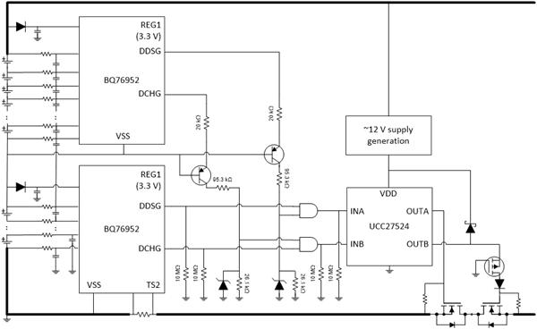
Like the communication signals, you will also need to correctly configure the protection signals. The BQ76952 provides logic-level outputs that match the controls used for the high-side FET drivers. These outputs are driven based on the local low-dropout regulator (LDO) of each monitor, which has a programmable voltage up to 5 V. As I mentioned before, combining these signals from stacked devices helps control low-side N-channel FETs, as shown in Figure 2.
 Figure 2 Combined protection solution
for BQ76952 battery monitors
Figure 2 Combined protection solution
for BQ76952 battery monitorsThe BQ76952 includes a shutdown mode for lower current consumption. To wake up from shutdown mode and return to normal operation, you can use one of two methods:
- Apply a voltage to the LD pin. A voltage on the LD pin normally occurs when a charger is connected.
- Pull the TS2 pin (which provides a weak 5-V level with a 5-MΩ source impedance while in shutdown) to VSS.
Make sure that all monitors in the stack include a wakeup method so that the entire system will function correctly. Applying a voltage to the LD pin on the device by attaching a charger will also induce wakeup, but it is important to add appropriate circuitry to limit the voltage at each pin to the specifications in the data sheet.
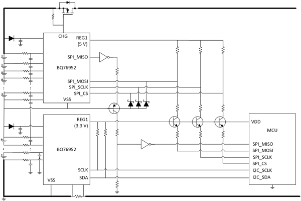
The BQ76952 supports up to 400-kHz I2C, Serial Peripheral Interface (SPI) and High-speed Data Input/Output (HDQ) communications. Each device is configurable with a separate I2C address. Using the ISO1640 isolator facilitates communication to the upper device(s), as in our Industrial Battery Management Module for 20S Applications Reference Design. Another option is level-shifting using discrete circuitry. Figure 3 illustrates an example using discrete circuitry with SPI communications.
 Figure 3 Serial communication in a
stacked solution with BQ76952 battery monitors
Figure 3 Serial communication in a
stacked solution with BQ76952 battery monitorsLoad detection with the BQ76952
The BQ76952 includes load-detection functionality to determine whether the load has been removed from a pack while the FETs are disabled. It is important to make sure that this signal is communicated across all devices in the stack, because otherwise the presence of a load determines the operating state of the battery monitors and all monitors in the stack should be in the same mode at any given time. You can use this detection functionality for recovery, after a short or overcurrent results in disabled FETs.
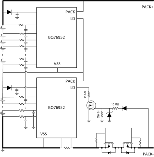
Load-detection functionality is designed for use with high-side FETs. With FETs off, the device will periodically source a 100-µA current out of the LD pin and measure the voltage of the pin. If the voltage is above a 4-V threshold, the device will detect whether the load has been removed. You can use this feature in a stacked configuration with low-side FETs and additional external circuitry. Figure 4 shows an example of a load-detection circuit.
 Figure 4 Load detection in a stacked
configuration with BQ76952 battery monitors
Figure 4 Load detection in a stacked
configuration with BQ76952 battery monitorsCell balancing with the BQ76952
When using multiple battery monitors, the cells connected to the bottom device may become imbalanced with the cells connected to the top device. To avoid imbalances caused by unequal power dissipation within the stack, configuring each device in the stack to enable the same set of modules or components internally will keep their power dissipation balanced. Take care to balance any external circuitry powered from the LDOs of the stacked devices. If this is a concern, it is ok to draw the supply voltage for each monitor and their associated LDOs from the top of the stack.
A random cell-attach feature means that the device will still function as expected, regardless of how the battery cells are connected. This feature is not always supported in designs with multiple devices, however. Pay careful attention to the guidelines for each device and connect the cells properly, in a way that avoids blowing an inline fuse. The BQ76952 battery monitor supports production-line programming of settings into one-time programmable memory.
Conclusion
The emergence of battery power in industrial applications presents new engineering challenges. Because single battery monitors cannot support the high cell counts in these applications, stacking multiple devices is a necessity. TI’s latest portfolio of battery monitors can be stacked to meet this design requirement.
Additional resources
- Read the technical articles, “Improving voltage measurement accuracy in battery monitoring systems” and “Improving temperature measurement accuracy in battery monitoring systems.”
- Read the application report, “Easy Configuration of BQ76942, BQ76952 Battery Monitors.”
- Watch the training video series, “BQ76952 and BQ76942 battery monitors.”