SSZT074 May 2022 TMAG5123 , TMAG5170
- 1
-
2
- 3
- Myth No. 1: Only TMR Sensors Can Take In-plane Measurements.
- Myth No. 2: Hall-effect Switches Are Not Useful Replacements for Reed Switches.
- Myth No. 3: Hall-effect Sensors Are the Same as Hall Elements.
- Myth No. 4: It Is Easy to Tamper with Systems Using Hall-effect Sensors.
- Myth No. 5: Hall-effect Sensors Are Not Useful for Measuring Angles.
- Myth No. 6: Linear Hall-effect Sensors Are Not Accurate.
Previously published on Electronic Design
In my previous Hall-effect sensor myths technical article, I focused on misconceptions about Hall-effect switches and latches, including common applications where designers could benefit from using Hall-effect sensors instead of other integrated circuits. The six myths in this article go a bit more in depth on the high-accuracy angle-measurement capabilities of Hall-effect sensors and their use in robotics systems for factory automation.
Myth No. 1: Only TMR Sensors Can Take In-plane Measurements.
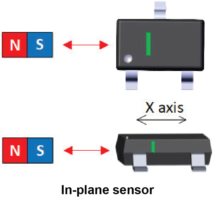
Designers typically consider tunnel magneto-resistance (TMR) sensors because of their high magnetic sensitivity, high linearity and low power consumption. Plus, TMR sensors can sense magnetic fields horizontally (or in plane) with the package. Most Hall-effect sensors available today are sensitive to perpendicular fields, but there are a few, such as the TMAG5123, that have in-plane sensing capability. Figure 1 shows the sensitivity directionality of an in-plane sensor. See the application brief, "Sensing Magnetic Fields In-Plane Versus Out-of-Plane."
 Figure 1 In-plane Sensitivity
Myth No. 2: Hall-effect Switches Are Not Useful Replacements for Reed Switches.
Reed switches are still prevalent in many applications. Common reed-switch applications include door and window sensors. The main drawback of reed switches in security alarm systems is the inability to detect tampering events. By using a linear 3D Hall-effect sensor, designers can allocate any channel not used for active measurement to detect this event.
Another example is in a refrigerator door to control the exact position, where the inside light is turned on or off. Hall-effect switches offer consistent open-and-close distance detection given their tight threshold hysteresis specifications.
Another major drawback of reed switches is their inability to use standard printed circuit board (PCB) assembly procedures. These switches must be hand-soldered onto the board, thus complicating the assembly process and increasing costs. Table 1 compares the two technologies.
| Specifications | Hall-effect switches | Reed switches |
|---|---|---|
| Magnet orientation sensitivity | Orthogonal and in plane | Parallel (same as in plane) |
| Current draw | Microampere range (low-frequency duty cycle) | Microampere to milliampere range (pulsed by microcontroller [MCU] general-purpose input/output) |
| Polarity sensitivity | Both poles (omnipolar) | Both poles |
| Hysteresis | Single-digit millitesla range | 40%-95% variation |
| Switch loads directly? | Requires additional circuitry | Yes (up to 3 A) |
| Response time | ≅10 µs | 25 µs to 100 µs |
| Life expectancy | Effectively unlimited operations – limited by silicon life expectancy | From thousands to billions of operations depending on load |
| Shock susceptibility | None | Yes |
| Assembly | Standard PCB assembly | Manual assembly with high yield loss (10%) |
| Operating temperature | –40°C to 125°C | –55°C to 200°C |
Myth No. 3: Hall-effect Sensors Are the Same as Hall Elements.
It is not true that Hall elements are essentially the same as Hall-effect sensors. The Hall element, which requires bias circuitry and a differential amplifier, is the most basic structure needed to produce a usable voltage. In contrast to Hall-effect sensors, Hall elements do not have all supporting circuitry integrated into a single package.
Figure 2 shows the circuit implementation for both types of sensors. Hall elements are typically used for applications where accuracy is not critical, cost is of extreme importance, and a differential amplifier is nearby to minimize external noise coupling. Additionally, Hall elements have an inherent nonlinear variation over temperature, while Hall-effect sensors have built-in compensation to ensure stable measurements across a wide temperature range of –40°C to 125°C. For more information about Hall-effect sensors, see the article, "What is a Hall-effect sensor?"
 Figure 2 Circuit Implementation for a Hall Element (a) versus a Hall-effect Sensor (b)
Myth No. 4: It Is Easy to Tamper with Systems Using Hall-effect Sensors.
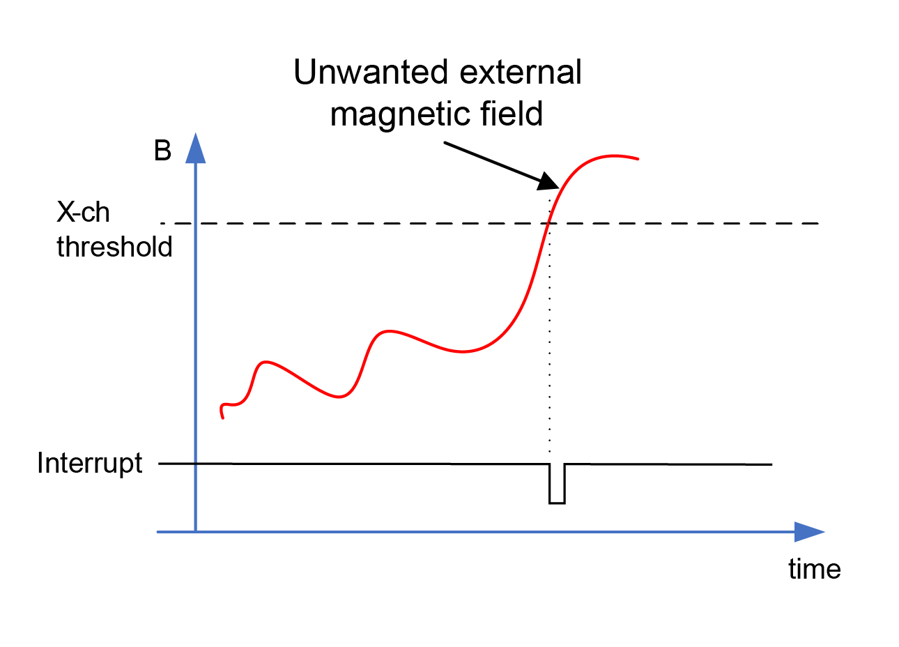
It is possible to tamper with systems using reed switches and basic Hall-effect switches – this is true. Large external magnetic fields can trick a system such that it functions as if everything is working properly. A good way to fix this is to use a linear 3D Hall-effect sensor. One axis monitors the presence of the intended magnet, while the other two channels detect external magnetic fields. Using a linear 3D sensor with a configurable magnetic threshold per channel provides more flexibility in setting the proper "tamper detection" threshold. The example in Figure 3 shows an MCU receiving an interrupt signal once the threshold is crossed.
 Figure 3 Tamper Detection Using a
Linear 3D Hall-effect Sensor
Figure 3 Tamper Detection Using a
Linear 3D Hall-effect SensorMyth No. 5: Hall-effect Sensors Are Not Useful for Measuring Angles.
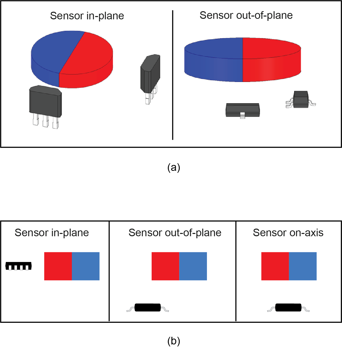
Hall-effect sensors are popular in many displacement applications, but they are also used for absolute angle measurements. By strategically positioning two single-axis linear Hall-effect sensors around a rotating dipole magnet, each sensor picks up a magnetic field vector that is out of phase with the other. With this information, it is easy to calculate the exact angle of the rotating magnet by using the arctangent function.
Figure 4a shows two implementations using linear sensors in two different package types. A more elegant way to perform angle measurement is with a single linear 3D Hall-effect sensor (see Figure 4b for various configurations). To learn about angle measurements, read "Absolute Angle Measurements for Rotational Motion Using Hall-Effect Sensors" and "Angle Measurement With Multi-Axis Linear Hall-Effect Sensors."
 Figure 4 Absolute Angle Measurement
Using Two Single-axis Linear Hall-effect Sensors (a) and One Linear 3D
Hall-effect Sensor (b)
Figure 4 Absolute Angle Measurement
Using Two Single-axis Linear Hall-effect Sensors (a) and One Linear 3D
Hall-effect Sensor (b)Myth No. 6: Linear Hall-effect Sensors Are Not Accurate.
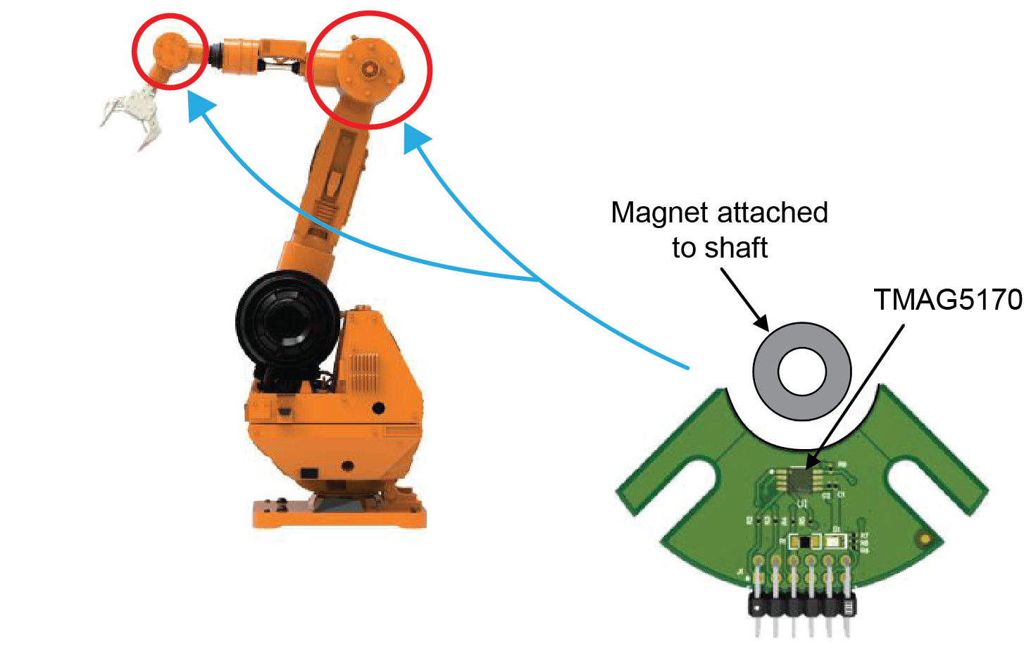
Linear Hall-effect sensors are cost-effective solutions that provide reliable magnetic information. Users of such sensors know this fact, but often consider other technologies to meet their high-accuracy requirements. For example, industrial robot arms must be precisely positioned in relation to their target object(s), and using a high-accuracy linear 3D Hall-effect sensor such as the TMAG5170 provides the precision needed for these applications (Figure 5). Additionally, both the high precision and low-sensitivity drift over temperature of the TMAG5170 potentially eliminate the need for system-level calibration.
 Figure 5 A Linear 3D Sensor in a
Robotic Arm Application
Figure 5 A Linear 3D Sensor in a
Robotic Arm ApplicationI hope you have enjoyed my articles debunking commonly held myths about Hall-effect sensors. These sensors continue to gain popularity in automotive and industrial applications through their high accuracy and increasing variety of integrated functions and diagnostics.