-
Prototype Motor Drive System for Autonomous Industrial Mobile Robots SPRACY8 September 2021 TMS320F2800132 , TMS320F2800133 , TMS320F2800135 , TMS320F2800137 , TMS320F2800152-Q1 , TMS320F2800153-Q1 , TMS320F2800154-Q1 , TMS320F2800155 , TMS320F2800155-Q1 , TMS320F2800156-Q1 , TMS320F2800157 , TMS320F2800157-Q1 , TMS320F280025C , TMS320F280033 , TMS320F280034 , TMS320F280034-Q1 , TMS320F280036-Q1 , TMS320F280036C-Q1 , TMS320F280037 , TMS320F280037-Q1 , TMS320F280037C , TMS320F280037C-Q1 , TMS320F280038-Q1 , TMS320F280038C-Q1 , TMS320F280039 , TMS320F280039-Q1 , TMS320F280039C , TMS320F280039C-Q1
Prototype Motor Drive System for Autonomous Industrial Mobile Robots
Trademarks
C2000 and Launchpad are trademarks of Texas Instruments.
All trademarks are the property of their respective owners.
1 Introduction
The global autonomous guided vehicle (AGV) and autonomous mobile robot (AMR) market is expected to skyrocket as factory automation applications increasingly adopts mobile robots in day-to-day operational activities.
A new definition of mobile robots have also emerged which is the Industrial Mobile Robot, this definition is a consolidation of AMR and AGV robots and defines these now as Type A,B,C IMR robots and the traditional AGV robot, the details of this effort can be seen in the ANSI/RIA R15.08 standard.
Over the past few decades MCUs have been controlling motors which have evolved beyond simple commutation of the universal motor. Now there are many MCUs available to developers who seek to create low-cost, high-performance systems. Through complex control algorithms, systems have improved power efficiency, more accurate speed/position control and higher torque while doing so in the most cost-effective manner. Many of the motors controlled by MCUs are three-phase synchronous and are generally controlled using a method call field-oriented control (FOC) to maximize efficient torque production.
TI’s three-phase motor drive systems simplify designing motor control applications, where low-cost development boards provide a platform for engineers to quickly design a prototype motor drive system and bring to market their own motor control design. The C2000Ware MotorControl software development kit (SDK) unifies TI’s motor-control developments into a single product which supports the latest generation TMS320F280049C and TMS320F280025C series in the C2000™ platform. Real-time debug allows for the monitoring and changing of application variables in real time, making it easy to debug the complex control loop. Additionally, as these MCUs are code compatible across the C2000 platform so developers can make long-term code investments and reuse motor control designs for future cost savings.
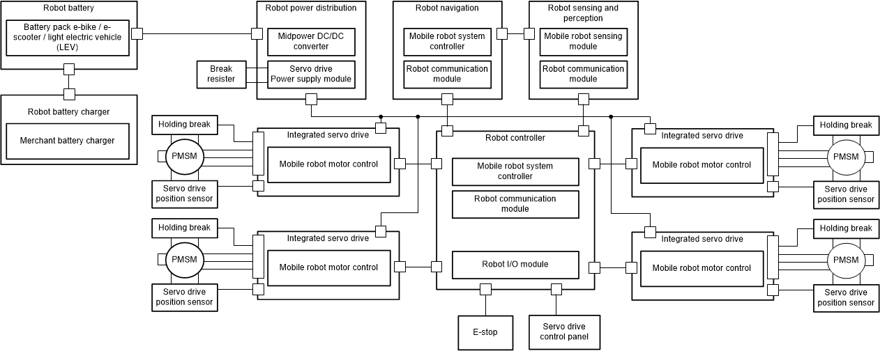
 Figure 1-1 Block Diagram of Typical 3-Phase
Motor Drive System
Figure 1-1 Block Diagram of Typical 3-Phase
Motor Drive System2 Functional Safety
The TMS320F280025C are Functional safety compliant products developed using an ISO 26262/IEC 61508 compliant hardware development process that is independently assessed and certified to meet ASIL D/SIL 3 systematic capability. Design packages are available to assist with safety system development and certification.
3 Motor Shaft Position Through eQEP
A majority of the time, mechanical angular positional sensors obtain the rotor position. Incremental encoders are one of the popular solutions to determine rotor position because they provide high-angular resolution and an accurate derived speed feedback over the whole speed range. These features enable incremental encoders to be frequently used for speed/position control in motor control applications.
Today, many servo motors come with built-in incremental position encoders, commonly referred to as ABZ encoders by the names of their output signals, A, B and I, to feedback the motor-shaft angle once you know the index. Table 3-1 shows the data pins required by the QEP peripheral that should be wired to the corresponding pins on the encoder.
| Pin Type | Pin Name | Pin Usage Per Motor |
|---|---|---|
| Digital | EQEOxA | 3 |
| EQEPxB | ||
| EQEPxI |
4 Host Motion Control Over CAN Bus
A controller area network (CAN) is used in many industrial/robotic protocols embracing CAN and ISO-11898:2003 as their physical layer. CAN is very popular due to the excellent noise immunity and clear cost advantages with regard to hardware and implementation. The LAUNCHXL-F280025C includes CAN 2.0b and can easily be implemented to receive a CAN message to update motor drive parameters such as speed, torque and position.
5 Labs
Permanent magnet synchronous motors (PMSM) offer numerous advantages and are a popular choice in motor drives and speed control requires three control layers to be performed. The innermost loop must determine precise rotor position to accurately commutate the stator flux. Once rotor position is known, the magnitude of the stator flux has to be calculated and controlled. Assuming that the current through the stator coils is proportional to the stator flux, then the control of the stator flux magnitude corresponds to control of the input current. Lastly, the outermost control loop regulates the motor speed.
This lab is built upon three incremental build levels:
- In the first build level you evaluate the open loop control of the system and introduce shaft position feedback from an incremental quadrature encoder.
- The second build level introduces tuning the PI controller using a step response.
- The third build level enables CAN communication to receive a new speed reference.
Build Level 1 uses open loop control (Volts/frequency) initially to run the motor. This method varies the stator voltage and frequency to control the motor speed without any motor feedback. This ensures the integrity of the hardware by running the motor, namely the PWM, ADC and QEP modules for hardware abstraction layer (HAL) setup.
 Figure 5-1 Graph for the Phase A Current
ADC Value
 Correct ADC current scaling is achieved through Equation 1. DRV8323RS uses three high performance current-sense amplifiers for low-side current measurement where the gain GCSA is user programmable to maximize the ADC input range. Phase voltage is also measured directly from each motor phase and the voltage feedback is based on resistor dividers (R1, R2), maximum phase voltage feedback measurable by the microcontroller is calculated using Equation 2. Since the FOC algorithm requires phase current and voltage as inputs, it is important to maximize the number of bits in the ADC converter output. Current waveforms (see Figure 5-1) can be observed using the graph function.
Motor shaft position feedback is introduced from the incremental encoder. The motor initially runs in open loop until while the QEP module waits for the index signal, a brief alignment resets the QEP count to zero and the initial position with respect to electrical zero is identified for run time corrections. This calibration angle can be formulated as shown in Equation 3.
This lab is useful to:
- Verify the hardware and software environment
- Read ADC values from current/voltage sensors
- Ensure correct handing of QEP signal
Build level 2 demonstrates a technique of tuning the proportional gain (Kp) and integral gain (Ki) for the current and speed controllers, this utilizes the graphing function of CCS to do step response testing. The default PI controller is just a starting point and needs tuning to meet the dynamic performance of the customer requirements.
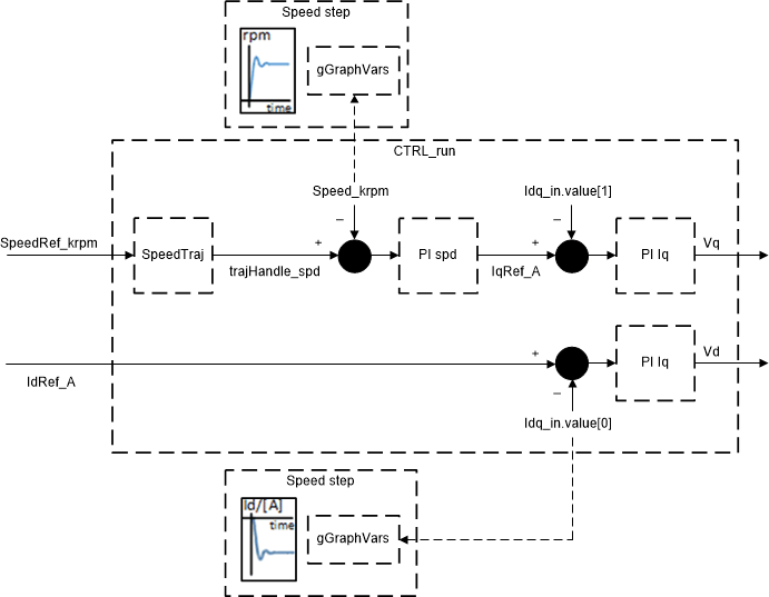
 Figure 5-2 Cascaded Speed and Current
Controller of InstaSPIN-FOC
Figure 5-2 Cascaded Speed and Current
Controller of InstaSPIN-FOCThe purpose is to generate a step response in the Id current controller to be almost independent of load torque changes. This removes the need for a load emulator like a dynamometer when trying to generate the step response in Iq.
Using the graph function, it is easy to tune both the current and speed controllers by applying a step response to the system. It is easy to verify the effects of the controller gains in your system and choose the gains that meet your system response, stability and efficiency targets. This step response generation is performed in real-time with the motor running in closed loop.
In FOC, the template provided the current and speed PI controller are cascaded as shown in Figure 5-2, therefore, to begin with the step response you need to start with the current controller. This is very efficient as it has a fast-inner current loop that is enclosed by a speed loop. In a real application, this should be running with loads as in a real system; however, you can begin using a light or no load. For example, in Figure 5-3, the values of Kp and Ki have been chosen to provide a fast response with no overshoot or ringing.
 Figure 5-3 Current Step Response Showing
no Overshoot at High Bandwidth
Figure 5-3 Current Step Response Showing
no Overshoot at High BandwidthA typical speed step response is given in Figure 5-4, remembering that you first need to tune the current control parameters as previously mentioned. In the same way as tuning the current controller, Kp and Ki are chosen to achieve the desired behavior. Here the parameters were chosen to achieve a quick response with no overshoot.
 Figure 5-4 Speed Step Response Showing no
Overshoot at High Bandwidth
Figure 5-4 Speed Step Response Showing no
Overshoot at High BandwidthBuild Level 3 introduces an isolated CAN transceiver, this demonstrates how to setup the can bus to receive a speed reference from a host motion controller. Here, an interrupt it generated every time the speed is updated from the host, the canISR then updates the system with a new speed reference. This can easily be modified to send additional motor control parameters that you may want.
6 Summary
First, this document shows how to run the motor in open loop to test the integrity of the hardware, ADC and PWM modules, for hardware abstraction layer (HAL) setup. Second, the document shows how to configure the current and speed step response to fit customer specifications is shown. PI controller tuning can be chosen to achieve the system performance required, ensuring the system is no regulating the current/speed too fast or slow. Lastly, CAN communication is implemented, whereby a speed reference can be sent by a host motion controller, such as in a real system.
Given its system-level integration and performance, the F28002x is well positioned for integration into motor drive systems. Furthermore, with the ability to support two servo motors with feedback, this C2000 controlled offers twice as much value. To get started quickly on designing your own motor drive prototype, order the C2000 MCU F280025C Launchpad™ and the BOOSTXL-DRV8323RS from the TI store. Project files can be found in C2000 Ware MotorControl SDK, in the solutions folder servo_drive_with_can.
IMPORTANT NOTICE AND DISCLAIMER
| TI PROVIDES TECHNICAL AND RELIABILITY DATA (INCLUDING DATASHEETS), DESIGN RESOURCES (INCLUDING REFERENCE DESIGNS), APPLICATION OR OTHER DESIGN ADVICE, WEB TOOLS, SAFETY INFORMATION, AND OTHER RESOURCES “AS IS” AND WITH ALL FAULTS, AND DISCLAIMS ALL WARRANTIES, EXPRESS AND IMPLIED, INCLUDING WITHOUT LIMITATION ANY IMPLIED WARRANTIES OF MERCHANTABILITY, FITNESS FOR A PARTICULAR PURPOSE OR NON-INFRINGEMENT OF THIRD PARTY INTELLECTUAL PROPERTY RIGHTS. |
| These resources are intended for skilled developers designing with TI products. You are solely responsible for (1) selecting the appropriate TI products for your application, (2) designing, validating and testing your application, and (3) ensuring your application meets applicable standards, and any other safety, security, or other requirements. These resources are subject to change without notice. TI grants you permission to use these resources only for development of an application that uses the TI products described in the resource. Other reproduction and display of these resources is prohibited. No license is granted to any other TI intellectual property right or to any third party intellectual property right. TI disclaims responsibility for, and you will fully indemnify TI and its representatives against, any claims, damages, costs, losses, and liabilities arising out of your use of these resources. |
| TI’s products are provided subject to TI’s Terms of Sale (www.ti.com/legal/termsofsale.html) or other applicable terms available either on ti.com or provided in conjunction with such TI products. TI’s provision of these resources does not expand or otherwise alter TI’s applicable warranties or warranty disclaimers for TI products. |
| Mailing Address: Texas Instruments, Post Office Box 655303, Dallas, Texas 75265
Copyright © 2021, Texas Instruments Incorporated |