SNVA559C September 2012 – February 2019 LM2574 , LM2575-N , LM2575HV , LM2576 , LM2576HV , LM2577
-
Switching regulator fundamentals
- Trademarks
- 1 Switching Fundamentals
- 2 Switching Converter Topologies
- 3 Application Hints for Switching Regulators
- 4 Application Circuits
- 5 References and Related Products
- Revision History
3.1 Capacitor Parasitics Affecting Switching Regulator Performance
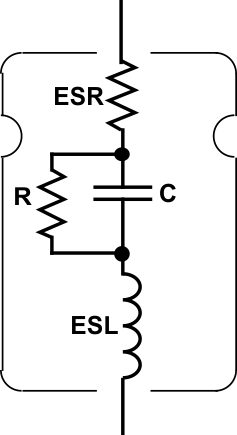
All capacitors contain parasitic elements which make their performance less than ideal (see Figure 16).
 Figure 16. Capacitor Parasitics
 Summary of Effects of Parasitics:
- ESR: The equivalent series resistance (ESR) causes internal heating due to power dissipation as the ripple current flows into and out of the capacitor. The capacitor can fail if ripple current exceeds maximum ratings.
- ESL: The effective series inductance (ESL) limits the high frequency effectiveness of the capacitor. High ESL is the reason electrolytic capacitors need to be bypassed by film or ceramic capacitors to provide good high-frequency performance.
Excessive output voltage ripple will result from high ESR, and regulator loop instability is also possible. ESR is highly dependent on temperature, increasing very quickly at temperatures below about 10°C.
The ESR, ESL, and C within the capacitor form a resonant circuit, whose frequency of resonance should be as high as possible. Switching regulators generate ripple voltages on their outputs with very high frequency (>10 MHz) components, which can cause ringing on the output voltage if the capacitor resonant frequency is low enough to be near these frequencies.