SNLU313 August 2022 DP83TG720R-Q1 , DP83TG720S-Q1
2.2 SGMII Differential Simulation
This example will show how to simulate the SGMII differential interface. Most of the configuration will be the same as the above example, so refer to the previous section for more detailed direction.
- Create a schematic in this
fashion, using an S4P model of a differential FR4 trace for the transmission
line.
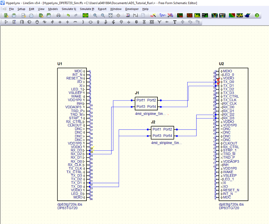
- Double click U1 and U2 and select the dp83tg720s.ibs model.
- Open the Manage model selector window for U1. Notice pins 23 and 24 have the ibis_sgmii_tx model selected, and are notated as a diff twin pair.
- Create a 625MHz PRBS-9 stimuli for the SGMII pins and assign them to pins 23 and 24.
- Open the simulation window and
select the box next to pin 32. The Blue and Green traces show the individual
trace waveforms, while the red shows math (pin 32 – pin 33).
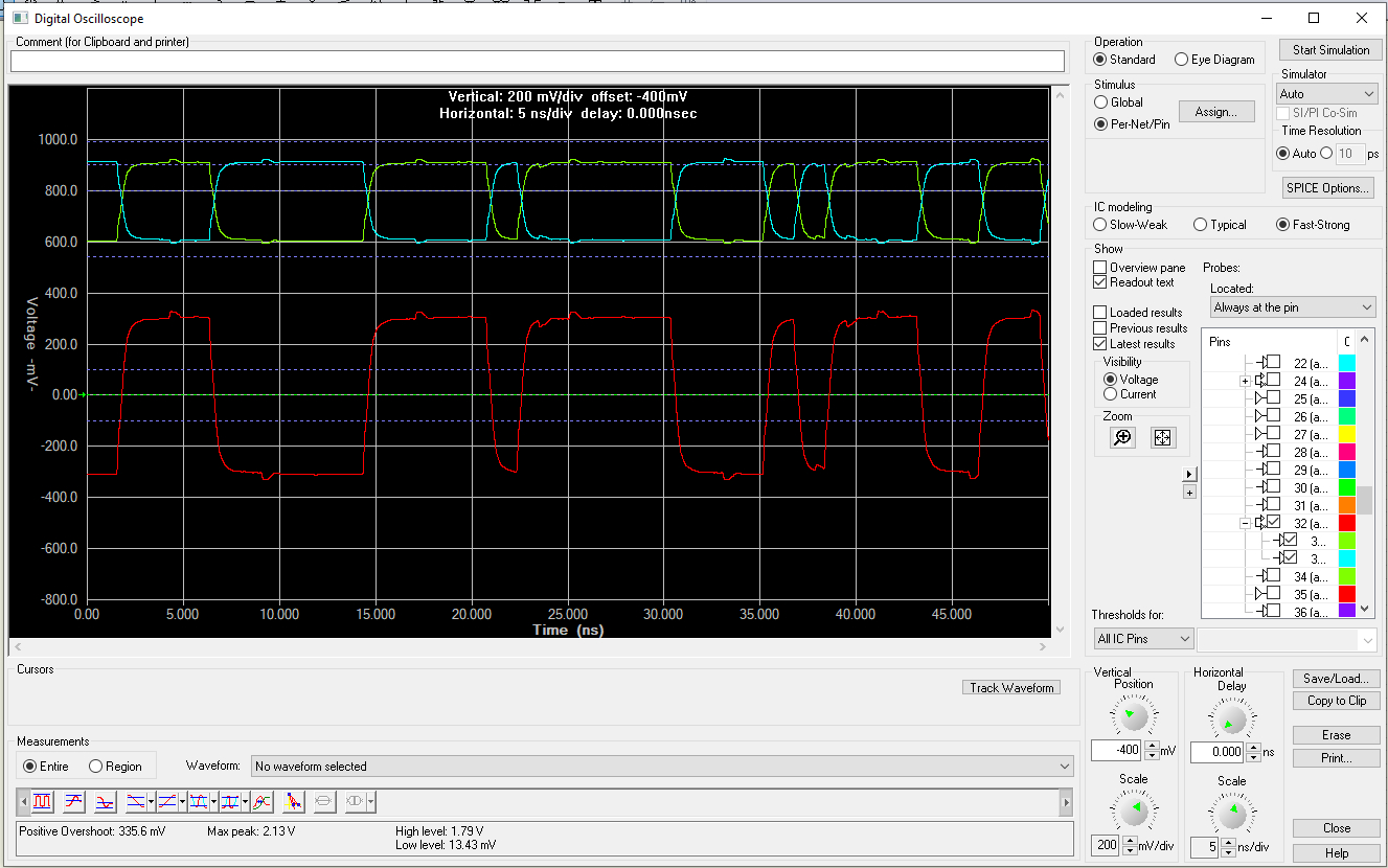
- Take measurements and change the configuration as desired.