SNLA399 July 2022 OPA607
2.3 Data Acquisition
 Figure 2-4 Block Diagram with Charge
Bucket
Figure 2-4 Block Diagram with Charge
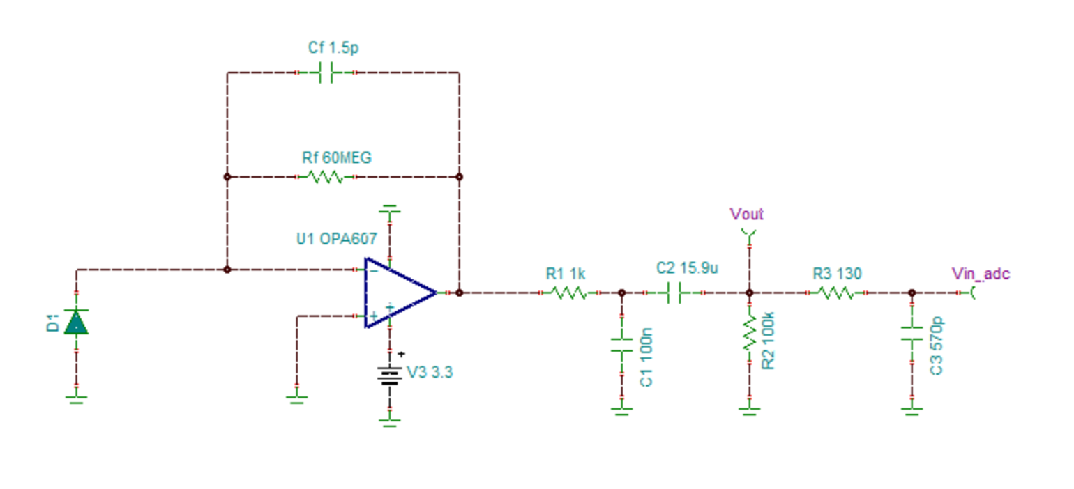
BucketIt is assumed that the output voltage of the analog front end is acquired using a single-ended 10-bit ADC available on MSP430G2x53 microcontroller board. The voltage reference of the ADC is 3 V and analog signal sampled at a rate of 10 ksps (100 µs), satisfying the Nyquist criteria fsample ≥ 2 fmax_signal. ADC has an input capacitance of 27 pF, resistance of 1 kΩ, maximum conversion time of 3.5us. The sample and hold circuit can be modeled using RC low-pass filter during the sampling time tsample (100 µs - 3.5 µs = 96.5 µs). It is calculated that a charge bucket of 130 Ω and 570 pF is required to provide enough charge at the input of ADC to match the input voltage. For more details on charge bucket see TI Precision Lab Videos on SAR ADC Input Driver Design.
The results show that the signal chain and charge bucket are able to drive the 10 bit ADC within 0.5 LSB accuracy.
The measurement range supported by the signal chain is dependent upon the ADC bit resolution and reference voltage as discussed in the following topics.