-
Linear Hall-Effect Sensor Angle Measurement Theory, Implementation, and Calibration SLYA036B July 2018 – November 2021 DRV5053 , DRV5053-Q1 , DRV5055 , DRV5055-Q1 , DRV5056 , DRV5056-Q1 , DRV5057 , DRV5057-Q1
-
Linear Hall-Effect Sensor Angle Measurement Theory, Implementation, and Calibration
- Trademarks
- 1Introduction
- 2Overview
- 3Device Descriptions
-
4Methods
- 4.1 Uncalibrated Implementations
- 4.2 Peak Calibrated Implementations
- 4.3 Lookup Table Calibration Implementations
- 4.4 Peak Calibrated Plus Lookup Table Hybrid
- 5References
- 6Revision History
- IMPORTANT NOTICE
Linear Hall-Effect Sensor Angle Measurement Theory, Implementation, and Calibration
Trademarks
All trademarks are the property of their respective owners.
1 Introduction
Linear Hall effect sensors measure the strength of a magnetic field and output a voltage proportional to that measurement. Based on the degree range and resolution needed, one or more linear Hall sensors can be used to determine the magnet direction. This application report covers angle measurements using no calibration, peak calibration, lookup table calibration, and a hybrid method of both the peak calibrated and lookup table methods.
2 Overview
2.1 Types of Magnetization
The two main types of magnetization in permanent magnets are axial and diametric. This terminology makes most sense when talking about discs, cylinders, and ring magnets. Axial magnets have north and south poles that are on the flat surfaces of the magnet. Diametric magnets have north and south poles that are on the rounded edges of the magnet.
Some examples of axially magnetized magnets are the two left magnets in Figure 2-1 and the two left magnets in Figure 2-2.
Some examples of diametrically magnetized magnets are the two right magnets in Figure 2-1 and the two right magnets in Figure 2-2.
Other magnet types are typically referred by shape, such as block and sphere magnets (Figure 2-3 and Figure 2-4), or by unique polarity, for example a multipole ring magnet (Figure 2-5).
2.2 Types of Magnets
 Figure 2-1 Disc and Cylinder Magnets
 Figure 2-2 Ring Magnets
 Figure 2-3 Block Magnets
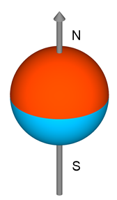 Figure 2-4 Sphere Magnet
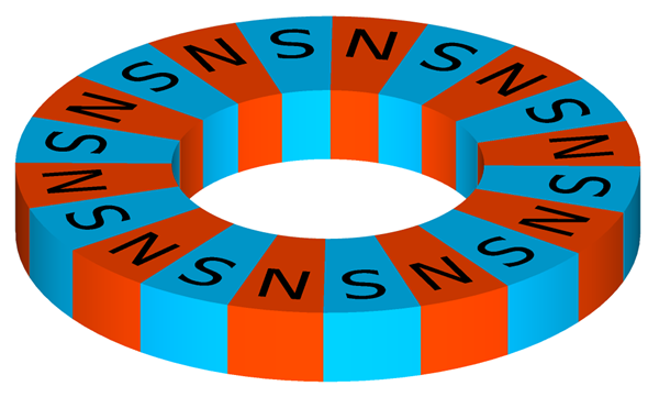 Figure 2-5 Multipole Ring Magnet
3 Device Descriptions
When using linear Hall effect sensors to measure angles, a bipolar sensor is generally most practical to use, although unipolar sensors can still be used for limited-angle measurements. Bipolar sensors respond to both the north and south poles of a magnet, and allow for wider-angle measurements. Unipolar sensors respond to one pole of the magnet allowing for only half of the movement range. The following subsections list some of the linear Hall effect devices from TI.
3.1 2.5-V to 38-V, Bipolar Hall Effect Sensor Family: DRV5053 and DRV5053-Q1
The DRV5053 is a chopper-stabilized Hall effect sensor that offers a magnetic sensing solution with superior sensitivity stability over temperature and integrated protection features.
The 0-V to 2-V analog output responds linearly to the applied magnetic flux density, and distinguishes the polarity of magnetic field direction. A wide operating voltage range of 2.5 V to 38 V with reverse polarity protection up to –22 V makes this device suitable for a wide range of industrial and consumer applications.
Internal protection functions are provided for reverse-supply conditions, load dump, and output short circuit or overcurrent.
The DRV5053-Q1 is the automotive-grade version of the DRV5053.
3.2 High-Accuracy, 3.3-V or 5-V, Ratiometric, Bipolar Hall Effect Sensor Family: DRV5055 and DRV5055-Q1
The DRV5055 is a linear Hall effect sensor that responds proportionally to magnetic flux density. This device can be used for accurate position sensing in a wide range of applications.
The device operates from 3.3-V or 5-V power supplies. When no magnetic field is present, the analog output drives half of VCC. The output changes linearly with the applied magnetic flux density, and four sensitivity options enable maximal output voltage swing based on the required sensing range. North and south magnetic poles produce unique voltages.
Magnetic flux perpendicular to the top of the package is sensed, and the two package options provide different sensing directions.
The device uses a ratiometric architecture that can eliminate error from VCC tolerance when the external analog-to-digital converter (ADC) uses the same VCC as a reference. Additionally, the device features magnet temperature compensation to counteract magnet drift for linear performance across a wide –40°C to +125°C temperature range.
The DRV5055-Q1 is the automotive-grade version of the DRV5055.
3.3 High-Accuracy, 3.3-V or 5-V, Ratiometric, Unipolar Hall Effect Sensor Family: DRV5056 and DRV5056-Q1
The DRV5056 is a linear Hall effect sensor that responds proportionally to flux density of a magnetic south pole. The device can be used for accurate position sensing in a wide range of applications.
The devices features a unipolar magnetic response. The analog output drives 0.6 V when no magnetic field is present, and increases when a south magnetic pole is applied. This response maximizes the output dynamic range in applications that sense one magnetic pole. Four sensitivity options further maximize the output swing based on the required sensing range.
The device operates from 3.3-V or 5-V power supplies. Magnetic flux perpendicular to the top of the package is sensed, and the two package options provide different sensing directions.
The device uses a ratiometric architecture that minimizes error from the VCC tolerance when the external analog-to-digital converter (ADC) uses the same VCC as a reference. Additionally, the device features magnet temperature compensation to counteract magnet drift for linear performance across a wide –40°C to +125°C temperature range.
The DRV5056-Q1 is the automotive-grade version of the DRV5056.
4 Methods
Table 4-1 shows a summary of the angle measurement methods discussed in this application report. For the column labeled Magnet Placement Orientation Required?, the term Approximately means that the magnet must be oriented during placement, but not very precisely. For more information about each method, see the associated sections linked in Table 4-1.
When trying to achieve high accuracy and resolution with 360° rotation, the Peak + Lookup Hybrid method is easier to implement than the standard lookup table. The Peak + Lookup Hybrid method is used for the DRV5055-ANGLE-EVM.
| Calibration Method | Recommended Magnet Options | Magnet Placement Orientation Required? | Accuracy Improved by Adding: | # Sensors Needed | Estimated Accuracy Peak-to-Peak Error (Based on measured data with a DRV5055) | Complexity | ||
|---|---|---|---|---|---|---|---|---|
| 1 Sensor | 2+ Sensors | < 180° | 360° | |||||
| Uncalibrated | Diametrically magnetized disc or axially magnetized cylinder or block | Yes | Yes | Sensors | 1+ | 2+ | = 180° / #Sensors | Low |
| Peak Calibrated | Diametrically magnetized disc | Yes | Yes | N/A | 1 | 2 | ≈ 8° | Low |
| Lookup Table | Diametrically magnetized disc | Approximately | No | Calibration points | 1 | 2 | ≈ (Spacing Between Cal Points) / 8 | High |
| Peak + Lookup Hybrid | Diametrically magnetized disc | Approximately | No | Calibration points | 1 | 2 | ≈ (Spacing Between Cal Points) / 15 | Medium |
4.1 Uncalibrated Implementations
4.1.1 Overview
4.1.1.1 General Implementation
The peak amplitude of the signal is unknown with an uncalibrated system. Therefore, the only usable information from the sensor is whether VOUT is greater or less than VVCC / 2, as shown in Figure 4-1. This information indicates whether the magnet is pointing towards a degree range (or region) where the sensor is sensing more north or more south polarity. The number of regions for a system depends on the number of sensors used.
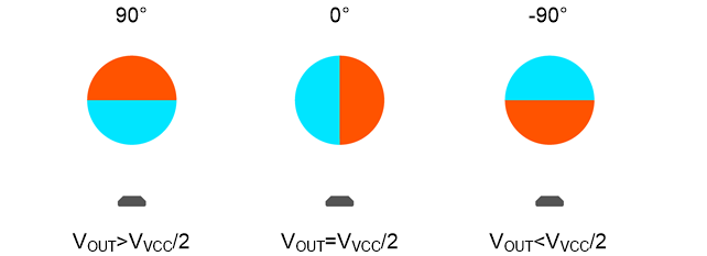 Figure 4-1 Uncalibrated Sensor Positions
4.1.1.2 Preferred Magnet Types
- Diametrically magnetized disc or cylinder
- Axially magnetized cylinder
- Block magnet
4.1.1.3 General Accuracy and Resolution
- Low accuracy
- Low resolution
- Results come in the form of general regions
- Accuracy can be improved by adding sensors
4.1.1.4 Considerations
- The magnet must be oriented to align desired regions.
- The boundary line for each sensor is at VOUT = VVCC / 2. If VVCC / 2 is measured, then either side of the boundary line may be chosen as the measured region.
- The uncalibrated implementations discussed here are for 360° rotation. For smaller ranges of movement, fewer regions are available.
4.1.2 One Bipolar Sensor, Uncalibrated
4.1.2.1 Specific Implementation
With one sensor, as shown in Figure 4-2, the sensor output voltage takes the form shown in Figure 4-3. Because there is no calibration phase, the peak amplitude is unknown.
 Figure 4-2 One Sensor Near Magnet
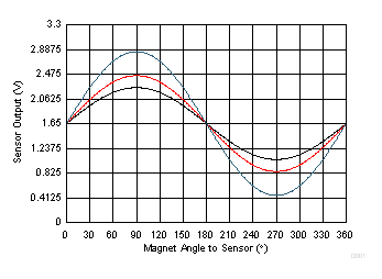 Figure 4-3 One Sensor Uncalibrated Data
4.1.2.2 Calculating Region
To determine the region that the magnet points towards, measure to see if VOUT is greater or less than VVCC / 2, as shown in Table 4-2.
| VOUT | Region |
|---|---|
| > VVCC / 2 | 0° to 180° |
| < VVCC / 2 | 180° to 360° |
4.1.2.3 Accuracy
The accuracy for this setup is the size of each region, 180°.
4.1.3 Two Bipolar Sensors 90° Apart, Uncalibrated
4.1.3.1 Specific Implementation
With two sensors 90° apart, as shown in Figure 4-4, the sensor output voltage takes the form shown in Figure 4-5. There is no calibration phase, so the peak amplitude is unknown; therefore, an example amplitude is shown.
 Figure 4-4 Two Sensors 90° Apart
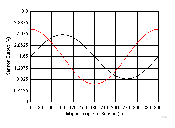 Figure 4-5 Two Sensors 90° Apart Uncalibrated Data
4.1.3.2 Calculating Region
To determine the region that the magnet points towards, measure VOUT for each sensor to see if VOUT is greater or less than VVCC / 2, as shown in Table 4-3.
| VOUT 1 | VOUT 2 | Region |
|---|---|---|
| > VVCC / 2 | > VVCC / 2 | 0° to 90° |
| > VVCC / 2 | < VVCC / 2 | 90° to 180° |
| < VVCC / 2 | > VVCC / 2 | 180° to 270° |
| < VVCC / 2 | < VVCC / 2 | 270° to 360° |
4.1.3.3 Accuracy
The accuracy for this setup is the size of each region, 90°.