SLVU135A June 2005 – June 2021 TPS62110
3.1 Layout
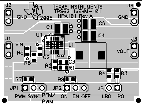
Figure 3-1 shows the board layout for the TPS62110EVM-101 PWB.
 Figure 3-1 Assembly Layer
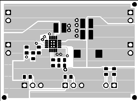
 Figure 3-2 Top Layer Routing
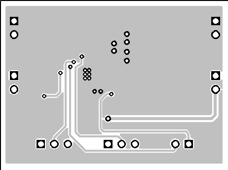
 Figure 3-3 Bottom Layer Routing
SLVU135A June 2005 – June 2021 TPS62110
Figure 3-1 shows the board layout for the TPS62110EVM-101 PWB.
 Figure 3-1 Assembly Layer
 Figure 3-2 Top Layer Routing
 Figure 3-3 Bottom Layer Routing