SLVAF10 March 2021 TPS1H000-Q1 , TPS1H100-Q1 , TPS1H200A-Q1 , TPS1HA08-Q1 , TPS1HB08-Q1 , TPS1HB16-Q1 , TPS1HB35-Q1 , TPS1HB50-Q1 , TPS2H000-Q1 , TPS2H160-Q1 , TPS2HB16-Q1 , TPS2HB35-Q1 , TPS2HB50-Q1 , TPS4H000-Q1 , TPS4H160-Q1
3.1 Background
In a PWM application, it is important to know the limits of timing that the HSS imposes on the final system design. Timing limitations affect how accurately load power can be controlled over the range of duty cycles. Since resistive and LED loads that convert load power to energy are intended to be detected by humans, some variation from ideal load power can often be tolerated. In cases where load power has to be more precisely controlled, such as in automotive lighting where luminous power is strictly regulated by governmental agencies, a designer may choose to use a lower PWM frequency in order to guarantee compliance with lightning standards regardless of HSS parameter skew.

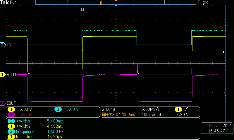
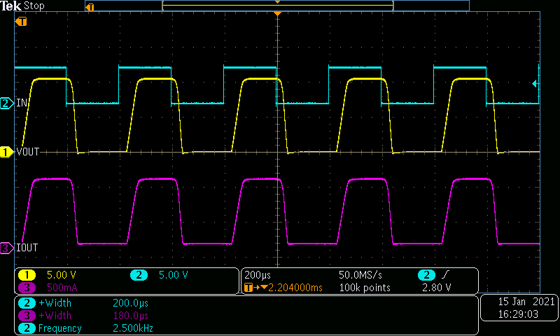
 Figure 3-1 Switching Too Fast in a TPS1H000-Q1 Resisitve
Load Setup.
 The principal phenomena that limit the pulse width a HSS can drive accurately are limited output slew-rate and propagation delay mismatch, also known as pulse-width distortion.