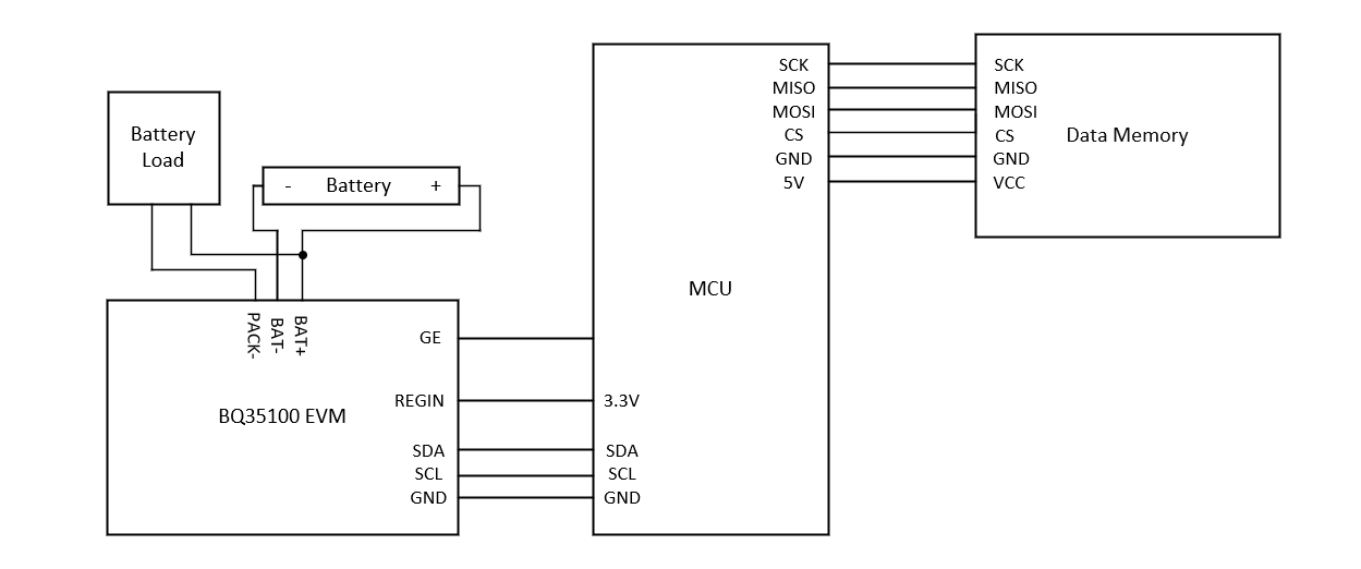
This application note examines how to configure the BQ35100 for End of Service (EOS) mode to accurately alert when a primary Li-SoCl2 battery needs to be replaced. To optimize the algorithm, impedance data needs to be collected using a microcontroller or other capable system to help calculate the data flash parameters for the EOS algorithm and alert functions.
All trademarks are the property of their respective owners.
It is difficult to gauge the remaining capacity of a lithium thionyl chloride battery because of the extremely flat open circuit voltage. However, the BQ35100 configured in EOS mode solves this challenge by using impedance data measured during short current pulses. This test shows the data that the BQ35100 can collect, and how that data is used to determine when a lithium thionyl chloride battery is nearing the end of life.
Figure 2-1 shows the wiring used for collecting impedance data. The BQ35100 EVM is connected using I2C communication, and data memory is connected using SPI communication, or any other available method. The BQ35100 EVM already implements pull-up resistors on the I2C communication lines so no external pull-up resistors are needed.
Any controller or MCU can be used for collecting the impedance data, there are only a few requirements:
Scaled resistance and measured impedance values are only updated when the gauge is in EOS mode. Using BQStudio is the easiest way to configure the gauge to EOS Mode.
First, set the gauge to unsealed mode if it was previously sealed by pressing UNSEAL in the Commands tab. Verify the gauge is unsealed by checking the [SEC1,0] bits of ControlStatus(). The gauge is unsealed when SEC1 is set high and SEC0 is set low. If the gauge was previously sealed, re-uploading the default .SREC file which was never sealed will stop the gauge from booting up in a sealed state.
Next, press NEW_BATTERY in the Commands tab. This resets any previous data stored for resistance and scale factors and needs to always be sent before a new battery is inserted. Never insert a partially drained primary battery for testing.
Finally, in the Data Memory Tab, press the Configuration button. In Operation Config A, set bit GMSEL1 to high and set bit GMSEL0 to low. This configures the gauge for EOS mode. It can also be configured for accumulation and SOH mode for different applications.
To gather resistance and impedance data, the microcontroller uses the addresses specified in the Technical Reference Manual (TRM). The I2C 8-bit address for the BQ35100 is 0xAA. The 7-bit address is 0x55. This address cannot be changed.
For both scaled resistance and measured impedance, the data is stored in little-endian format as unsigned integers. The command 0x16 is used to gather the scaled resistance data, and the command 0x22 is used to gather the measured impedance data. This is the most critical data to be extracted to calculate the appropriate EOS configuration for the system.
While in EOS mode, the gauge needs to be enabled before any major discharge of the battery occurs. For this test, the MCU gathers impedance data and writes the data to a data memory device. The testing procedure consists of the following steps:
The G_DONE bit is found in bit 6 if the CONTROL_STATUS command
For the gauge to take an accurate measurement of the voltage and current for estimating the resistance of the cell, the pulsed load must be at least 100-ms long and cause a 100-mV drop of the battery voltage. This constitutes the minimum requirement for a major discharge.
It is common for end equipment to use separate resistors from the expected load burst, which is typically RF dynamic load, to provide consistent current bursts for the gauge to learn the resistance. The gauge thrives on consistency of the measurements and does not require significant drain on the battery to perform the learning load burst.
Figure 6-1 shows an example of the impedance data that is collected by the gauge. This data shows a lithium thionyl battery starting at full capacity to be completely discharged. Towards the end of the battery’s life, there is a spike in the impedance which is characteristic of lithium thionyl chloride batteries and a strong indicator that the battery is nearing the end of battery life.
For testing purposes, the battery was discharged by 1% SOH at the maximum continuous discharge rate specified by the battery manufacturer after each learning pulse. After the 1% SOH discharge the battery was relaxed for 5 hours. Each learning pulse was 500 ms long and the current was set to 100 mA to meet the requirements of the pulse length and amplitude.
After performing a complete discharge of the primary cell and logging the resistance, the EOS parameters can be configured.
The only parameter that needs to be updated for initial EOS learning is the New Batt R Scale Delay, this needs to be set to a value after the passivisation layer is expected to be gone. The passivisation layer can be seen as the initial resistance measurement being higher than expected, and then decreasing after subsequent pulses. Once resistance stops decreasing and is flat, the passivisation layer has been removed.
Class | Subclass | Name | Type | Size | Min Value | Max Value | Default Value | Unit |
---|---|---|---|---|---|---|---|---|
EOS Data | Values | New batt R scale delay | Unsigned Integer | 1 | 0 | 255 | 2 | Readings |
EOS Data | Values | R Table Scale | Integer | 2 | -1 | -1 | -1 | – |
EOS Data | Values | R Table Scale Update Flag | Hex | 1 | 0×00 | 0×ff | 0×ff | – |
After the initial learning is setup, the most important value to configure from the resistance data is the EOS Trend Detection this determines when the gauge sets the [EOS] flag by comparing the Short Trend Average and Long Trend Average.
Class | Subclass | Name | Type | Size | Min Value | Max Value | Default Value | Unit |
---|---|---|---|---|---|---|---|---|
EOS Data | Values | R short trend filter | Unsigned Int | 1 | 1 | 255 | 251 | – |
EOS Data | Values | R long trend filter | Unsigned Int | 1 | 1 | 255 | 253 | – |
EOS Data | Values | EOS trend detection | Unsigned Int | 1 | 1 | 100 | 20 | – |
EOS Data | Values | EOS detection pulse count | Unsigned Int | 2 | 1 | 20000 | 120 | – |
EOS Data | Values | EOS detection pulse count Thrhd | Unsigned Int | 2 | 1 | 20000 | 120 | – |
EOS Data | Values | Short trend average | Unsigned Int | 4 | 1 | 8355712 | 0 | – |
EOS Data | Values | Long trend average | Unsigned Int | 4 | 1 | 8355712 | 0 | – |
To estimate the long and short filtered values we can use the following formulas from the TRM.
Short Trend Average = Impedance × 1/DF1 + Previous Impedance × (1–1/DF1)
Long Trend Average = Impedance × 1/DF2 + Previous Impedance × (1–1/DF2)
Where DF1 = 50, DF2 = 100, and Previous Impedance is the previously calculated Short Trend Average or Long Trend Average value.
To determine when the battery needs to be replaced, the following check is done which triggers the [EOS] flag.
Short Trend Average > Long Trend Average × (1 + EOS Trend Detection / 100)
When this occurs the [EOS] flag is set and cannot be cleared.
After the EOS flag is set, the battery needs to be replaced. The EOS alert indicates the battery is near end of life according to the customer settings of EOS Trend Detection and resistance increases.