SLUAAD0 September 2021 UCC28064A
- Trademarks
- 1Introduction
- 2Normal Theory of Multi Phases Control UCC28070 and UCC28064A Operation
- 3Achieving Adjustable Phase Control Operation with UCC28064A
-
4Achieving Multi Phases Control
Operation
- 4.1 Disable Feedback of Secondary (Connecting VSENSE and VREF Directly)
- 4.2 Disable Feedback of Secondary (Connecting VSENSE and VREF with Diode)
- 4.3 External 4 Multi-phase Mode Control Circuit of UCC28064A
- 4.4 Detail Operating for External Paralleling Two-Power Stages Control Circuit of UCC28064A
- 4.5 Test result for External Paralleling two power stages control circuit of UCC28064A
- 5Summary
- 6References
3 Achieving Adjustable Phase Control Operation with UCC28064A
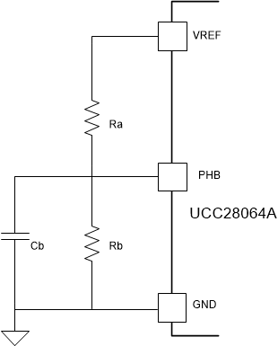
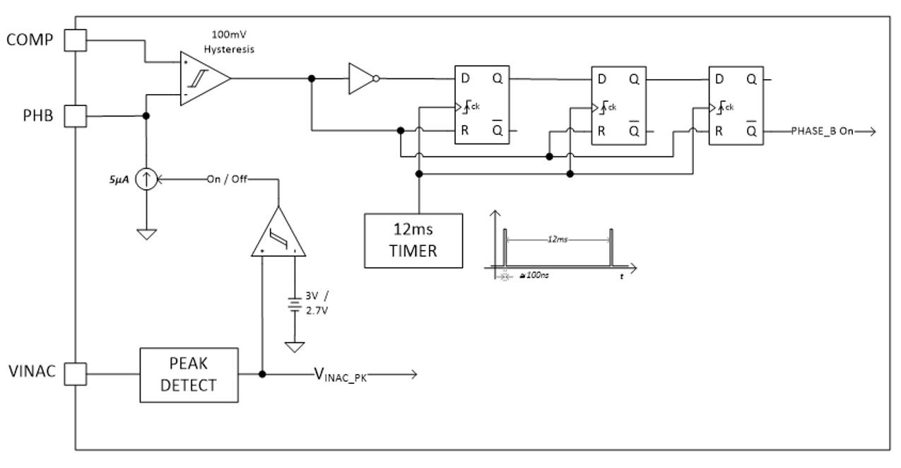
The voltage on the PHB pin can be set using a simple resistor divider connected to the VREF pin. Another important feature, that allows optimization of phase management is that it is possible to set different thresholds whether the PFC input voltage is in the range of 90 to 132 VRMS (US mains) or in the range of 180 to 265 VRMS (European mains). If the peak voltage sensed by the VINAC pin exceeds 3.5 V, the converter assumes that the input voltage is in the range of 180 to 265 VRMS and starts sourcing from PHB a small current (3µA typically) that increases the voltage on PHB pin.
 Figure 3-1 Original Adjustable Phase Control Circuit with
UCC28064A
 Figure 3-2 Internal Block of Phase
Control with UCC28064A