SLOA212A December 2014 – February 2016 RF430FRL152H
4 Antenna Design
The antenna coil inductance is measured at 1.84 µH as shown in Figure 7. To calculate the parallel tuning capacitors required, the resonant frequency formula in Equation 1 should be used. For further details on antenna tuning, see the RF430CL330H Practical Antenna Design Guide (SLOA197).
Equation 1. 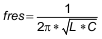
 Figure 7. Coil Inductance
 Figure 8 shows the measured resonant frequency at 13.66 MHz with 274.3 kHz. This results in a Q factor of less than 50 using the calculation shown in Equation 2. The read range of this reference board is 8cm using the TRF7970AEVM reader.
Equation 2. 
 Figure 8. Resonant Frequency