SLAAE30 July 2021 MSP430FR2355
2.4.3 Spikes and Noise
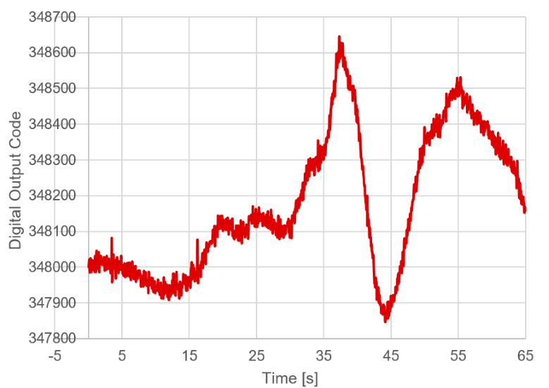
If you zoom in on the data waveform, you will see that the signal is still quite noisy. The more noise that can be removed, the better the signal to noise ratio will be. The signal chain has already been improved to reduce the noise, but because you are sampling the signal with an ADC, it is possible to perform additional data processing on the signal. For the software, this noise is characterized as two different types: spikes and ripples.
 Figure 2-5 PIR Sensor Signal Zoomed
In
Figure 2-5 PIR Sensor Signal Zoomed
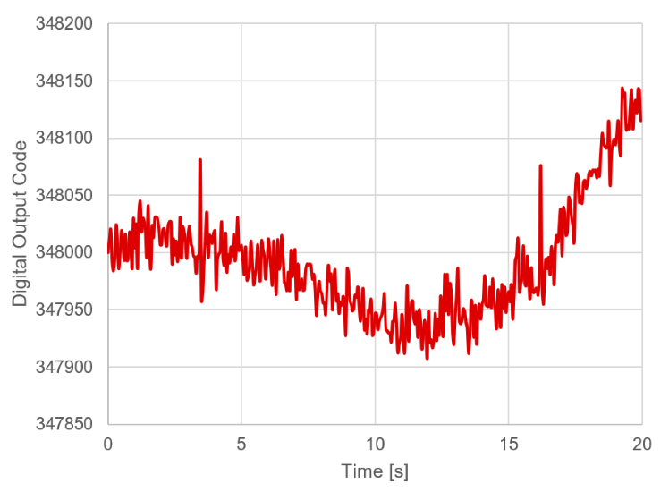
InFigure 2-6 shows two fairly large, random high-frequency spikes in the data. The samples are run though a “de-spiking” function that attempts to identify and remove these spikes and improve performance. This function basically looks at the last several samples captured in a window, and removes maximum and minimum values and therefore smoothing out any extreme "spikes" seen in the data.
 Figure 2-6 PIR Signal Spikes
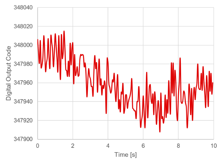
Figure 2-7 shows ripples and white noise. There is a place holder for a“de-rippling” function, but the current example software has not implemented this. All the data below was captured without it.
 Figure 2-7 PIR Signal
Ripples/Noise