SLAAE27 June 2021 MSP430FR2155 , MSP430FR2155
4.2 DC Motor Output
The DRV8837C is used to drive the DC motor for iris control. The nSLEEP pin is set by MSP430FR2155 to enable DC motor drive. IN1 and IN2 pins are driven by MSP430FR2155 to control the speed and direction of the motor rotation as shown in Table 4-2.
| nSLEEP | IN1 | IN2 | OUT1 | OUT2 | Function (DC Motor) |
|---|---|---|---|---|---|
| 0 | X | X | Z | Z | Coast |
| 1 | 0 | 0 | Z | Z | Coast |
| 1 | 0 | 1 | L | H | Reverse |
| 1 | 1 | 0 | H | L | Forward |
| 1 | 1 | 1 | L | L | Brake |
MSP430FR2155 generates the PWM input for IN1 and IN2 to control the motor's forward or reverse rotation. Duty cycle of PWM is calculated by the software based on the motor voltage required for the DC motor operation. Direction, PWM frequency, and time-out are configurable in the software.
Figure 4-6, Figure 4-7, and Figure 4-8 show the supply voltage (VCC), nSLEEP (enable pin), and the motor drive (IN1, IN2) for forward and reverse rotation. Figure 4-9, Figure 4-10, and Figure 4-11 show the voltage and current profiles for different PWM frequencies.
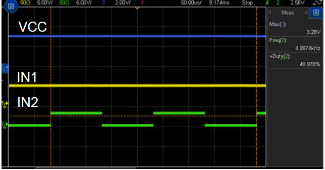 Figure 4-6 Inputs to Motor Driver: VCC, IN1,
IN2 for Reverse Direction
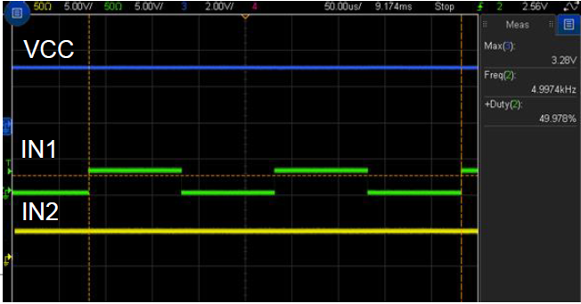 Figure 4-7 Inputs to Motor Driver: VCC, IN1,
IN2 for Forward Direction
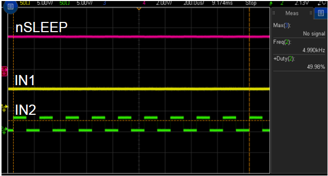 Figure 4-8 Inputs to Motor Driver: nSLEEP,
IN1, IN2
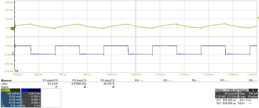 Figure 4-9 Voltage and Current, 50% Duty
Cycle, 10 kHz, Reverse Direction
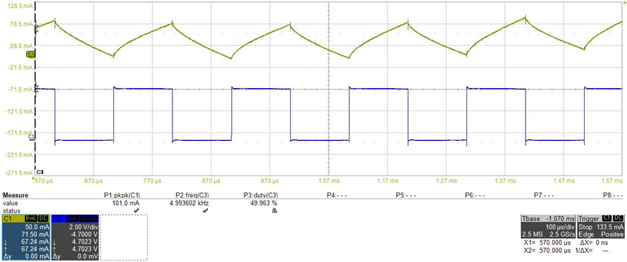 Figure 4-10 Voltage and Current, 50% Duty
Cycle, 5 kHz, Reverse Direction
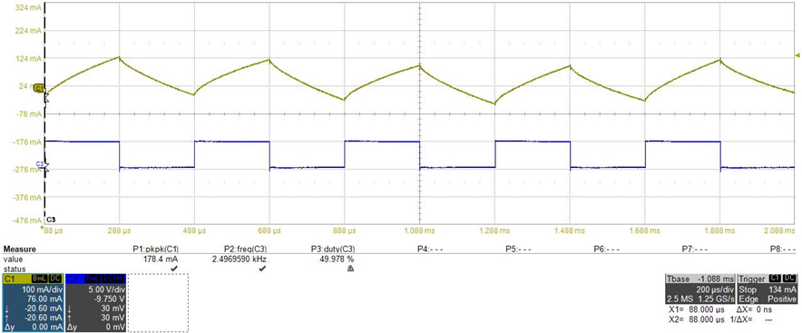 Figure 4-11 Voltage and Current, 50% Duty
Cycle, 2.5 kHz, Reverse Direction