SBVA097 February 2023 TLV758P
2.1 Bench Results
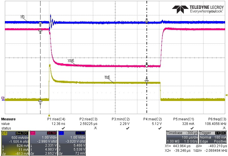
Performing a load transient is one method to test for current limit using a bench setup. The TLV758P has a current limit range of 530 mA up to 865 mA, which is given for the condition of VIN = VOUT(nom) + 1.0 V. When testing current limit, it is recommended to use a load that is approximately 50% higher than the maximum current limit to enter current limit. (See #FIG_FTD_Z4Q_FWB)
During the load transient event, there is a peak current value of 1.2 A, which is expected with the test conditions. The current limit circuit is a feedback loop which means there is a minimum response time which corresponds to the bandwidth of the feedback loop. Consequently, the device requires approximately 20 µs for the current limit circuit to activate, then it starts to regulate the output current to approximately 620 mA.
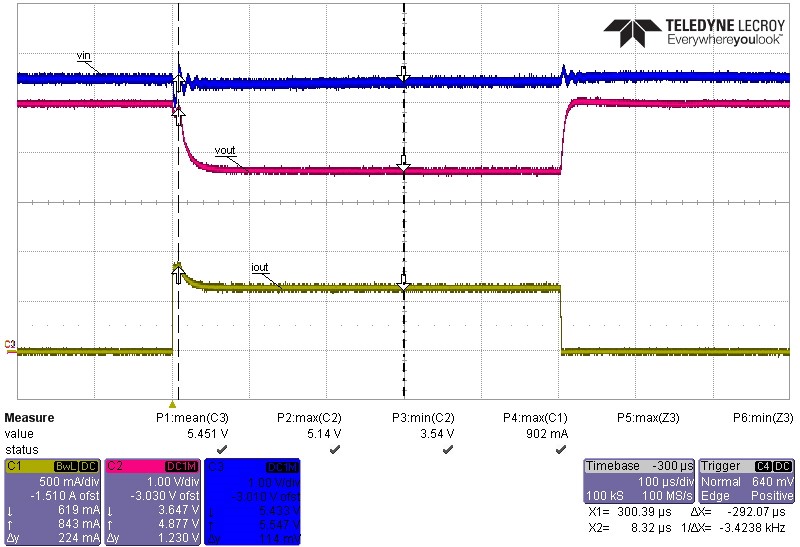
Similarly, #FIG_M55_JQQ_FWB shows a load transient with a smaller load. The peak current reaches 902 mA and then regulates the current to approximately 620 mA, while maintaining enough headroom between VIN and VOUT where VIN = VOUT + 0.5 V.
However, the TLV758P has a dropout specification of 130 mV when 3.3 V ≤ Vout ≤ 5.5 V. Because the LDO regulator provided enough headroom to avoid the dropuout condition (VIN = VOUT + 0.5 V), the current limit behavior of the above transients is almost identical with a regulated current of approximately 620 mA. This value is within the expected range of 530 mA to 865 mA in the TLV758P Electrical Characteristics table.
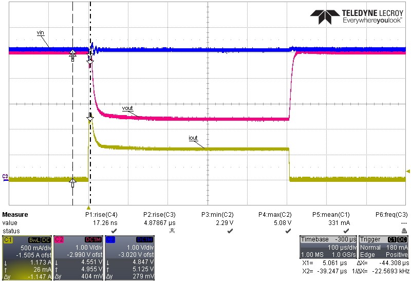
The same set of tests are performed during dropout operation by changing the input voltage to VIN = 5.13 V. When the test circuit uses a 3.9-Ω load, which is well above the normal current limit trip point, the current limit circuit behaves as expected as shown in #FIG_Y3F_XQQ_FWB.
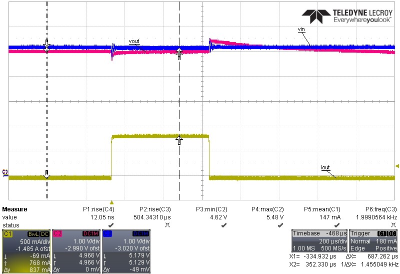
When the load equals 5.6-Ω, the regulator does not enter current limit protection mode as shown in #FIG_HNW_HRQ_FWB, and instead, the regulator performs expected for a normal load transient event. By comparing the results, the data clearly shows that during dropout operation as shown in #FIG_Y3F_XQQ_FWB and 2-4, the current limit trip point increases above 1 A due to a decrease of the sense current flowing through the internal RS resistor. During dropout operation when current limit engages, the regulated output current becomes approximately 620 mA.

| VIN = 5.5 V | VOUT(nom) = 5.0 V | RLOAD = 3.9 Ω |

| VIN = 5.13 V | VOUT(nom) = 5.0 V | RLOAD = 3.9 Ω |

| VIN = 5.5 V | VOUT(nom) = 5.0 V | RLOAD = 5.6 Ω |

| VIN = 5.13 V | VOUT(nom) = 5.0 V | RLOAD = 5.6 Ω |