SBOA426 March 2021 INA233
3 Bench Setup and Group Command Verification
Figure 3-1 shows the bench configuration that is used to verify that the PMBus group command can synchronize measurements among four INA233 devices. Vdiff is the input shunt voltage source and is time varying; Vcm is the common mode input voltage source and is set to 0V. Each INA233 is assigned a unique address and all four are connected in parallel to sample the same input source.
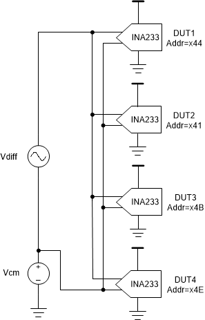 Figure 3-1 Bench Set-Up with Four INA233
Devices
Figure 3-1 Bench Set-Up with Four INA233
DevicesIn order to verify that the group command is synchronized, it makes sense to monitor when the ADC channels begin their conversions. However, there is no external indicator of the ADC conversion start that is available at the board level. In lieu of this, the best external indicator of synchronized conversions is the Conversion Ready signal, which can be brought out through the ALERT pin via setting the MFR_ALERT_MASK register. Therefore, the toggling of the ALERT pin will be used as an indicator of this functionality.
Note that potential differences in parasitic loading on the ALERT pins of the individual devices may impact the response timing. Also note that due to inherent variation in the device’s internal oscillator frequency, variation in the ALERT signals is expected (as shown in Figure 3-2 for a 8.2ms conversion case and Figure 3-3 for a 140us conversion case). Due to the cumulative effect of this variation over time, oscillator frequency variation leads to greater differences in completion time for longer conversions. Larger averaging number requires longer total conversion time, therefore similar greater difference in completion time can be expected as well.
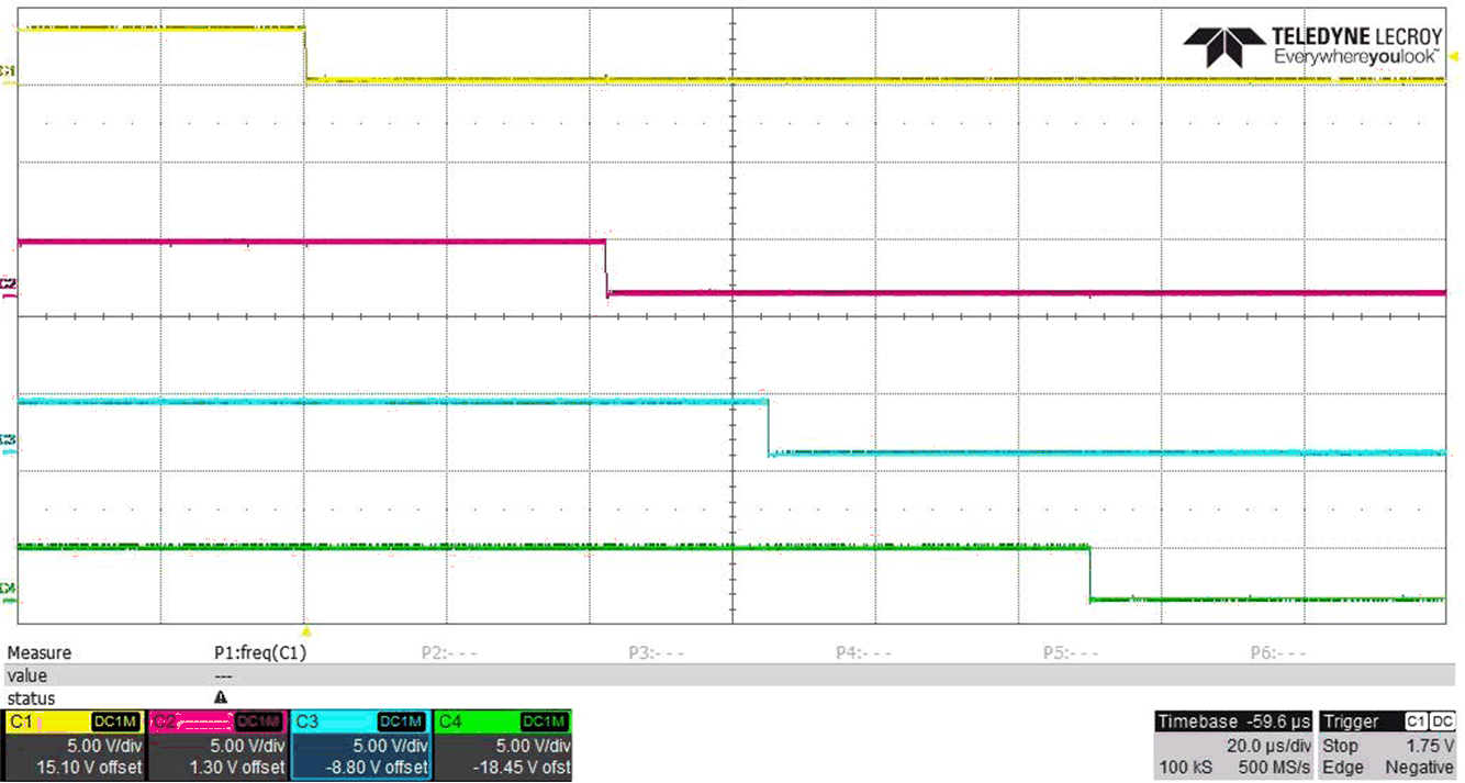 Figure 3-2 ALERT Signals with
8.2ms Conversion
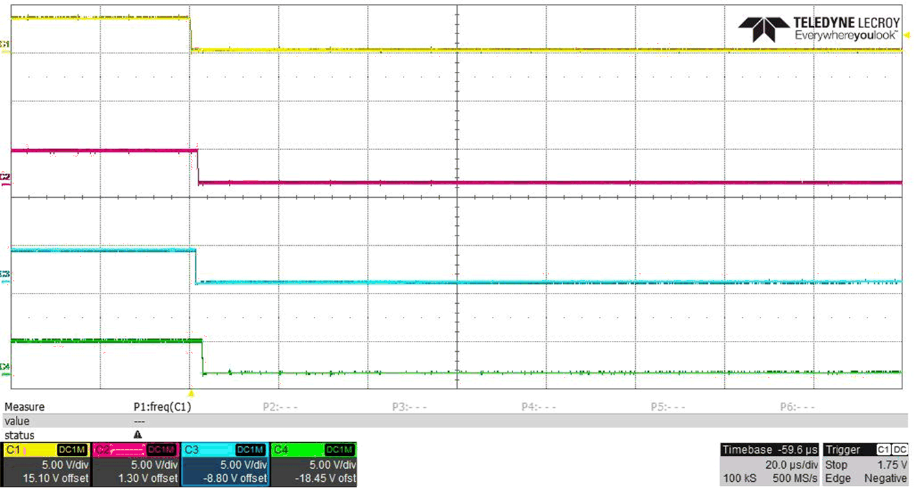 Figure 3-3 ALERT Signals with
140us Conversion
Figure 3-3 ALERT Signals with
140us ConversionAnother factor that affects the conversion completion time is the uncertainty in start time, because the internal system clock is not synchronized among descrete devices even if they are perfectly matched. This effect is best demonstrated with a persistent plot, where the conversion time is set to the shortest, as shown in Figure 3-4.
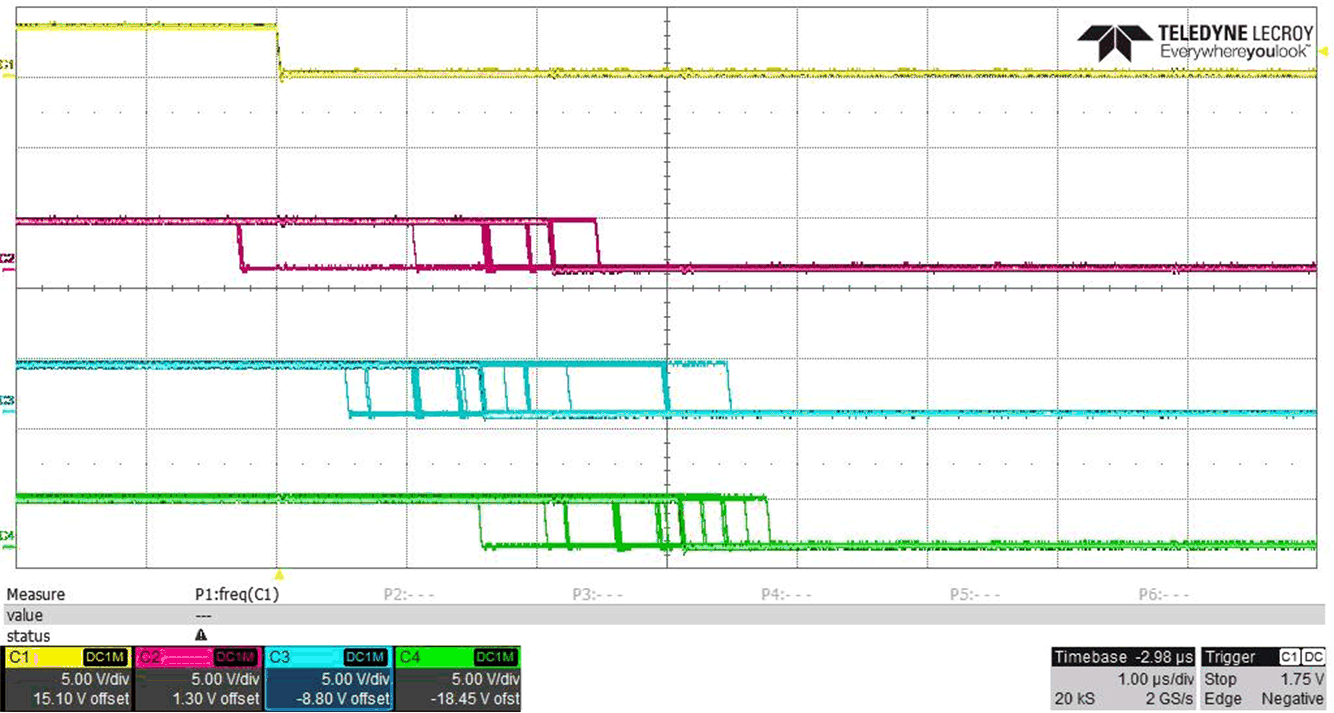 Figure 3-4 Persistent Plot of ALERT
Signals
Figure 3-4 Persistent Plot of ALERT
SignalsPMBus group command protocol requires all devices to execute their individual commands only upon receiving the STOP condition. Therefore, the order in which the devices in the group are addressed should have no effect on command execution order. Additional testing was completed to verify and show that there is no sequential relationship between the order the devices are addressed and the order of the ALERT signals. The variation in the timing of the ALERT signals comes only from the inherent variation of the internal oscillator frequency. Compare Figure 3-5 and Figure 3-6 below.
In Figure 3-5, the INA233 devices are addressed serially in the order of 1 through 4 (i.e. 1-2-3-4). ALERT pins are monitored for devices 1 and 4 as indicators of conversion complete. In Figure 3-6 the positions of devices 1 and 4 are swapped, and the addressing order becomes 4-2-3-1. Again, the ALERT pins are monitored for devices 1 and 4. Notice the relative position of the ALERT signal remains unchanged.
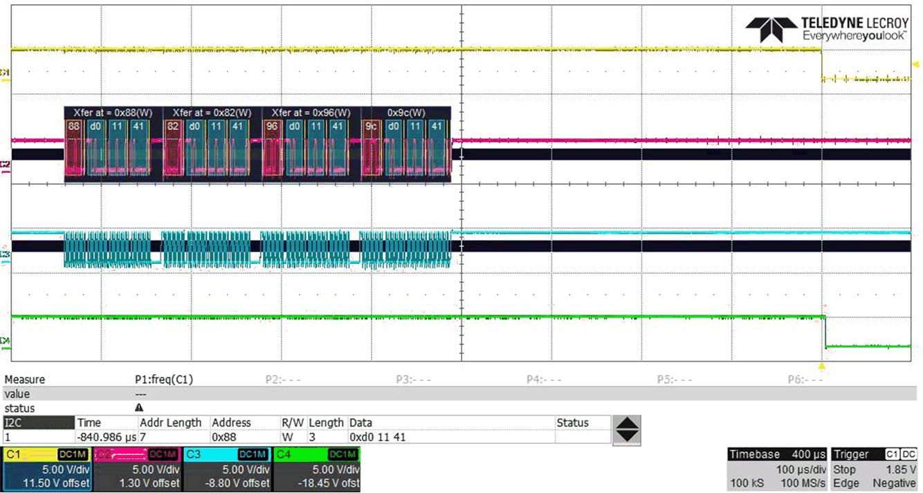 Figure 3-5 Addressing Order: 1, 2, 3,
4
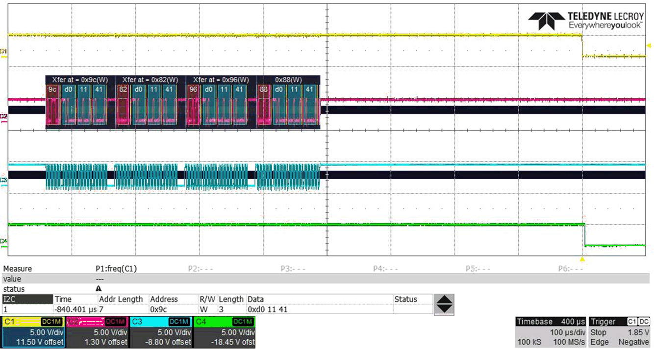 Figure 3-6 Addressing Order: 4, 2, 3,
1
Figure 3-6 Addressing Order: 4, 2, 3,
1Additional testing was completed to verify the robustness of the group command. In this experiment, large time delays were inserted in the addressing sequence of the devices on purpose; it is shown that these delays do not impact the synchronized behavior of the device. Figure 3-7 shows 1ms delays in the addressing sequence of the devices and Figure 3-8 shows the same 1ms delays with a changed addressing sequence. Both test set-ups result in synchronized measurements, with the variation in ALERT signals deterministically following each device as a result only of internal oscillator variation.
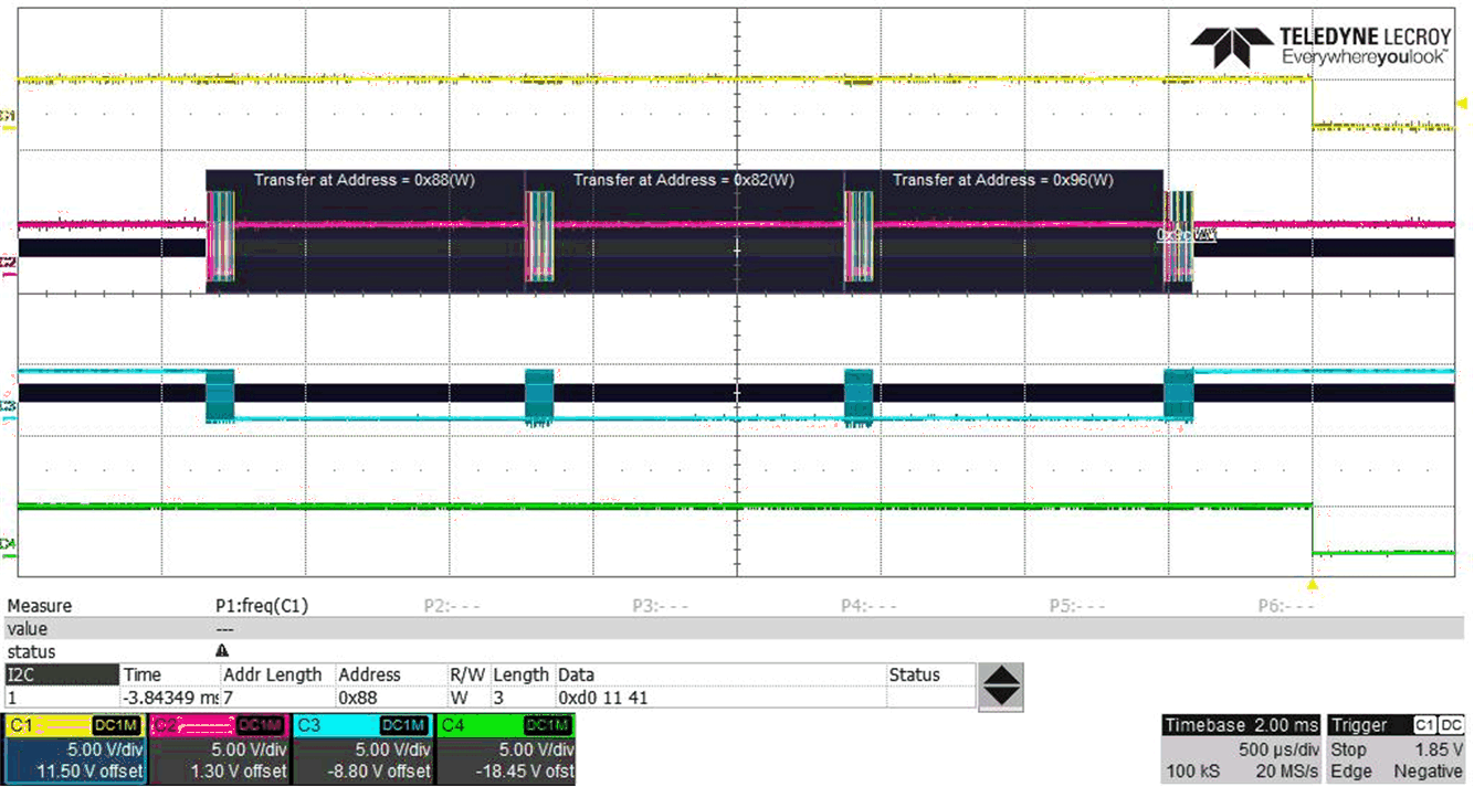 Figure 3-7 Large Delay and Addressing
Order: 1, 2, 3, 4
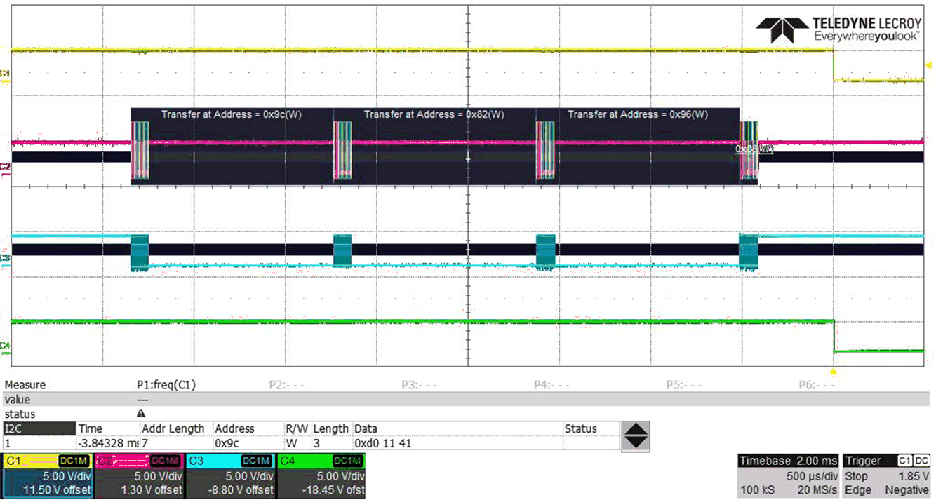 Figure 3-8 Large Delay and Addressing
Order: 4, 2, 3, 1
Figure 3-8 Large Delay and Addressing
Order: 4, 2, 3, 1The combination of the above results from the group command verification show that it is possible to execute synchronized measurements between multiple INA233 devices with a single command from the controller.