ZHCSGY8B October 2017 – July 2018 UCC21520-Q1
UNLESS OTHERWISE NOTED, this document contains PRODUCTION DATA.
- 1 特性
- 2 应用
- 3 说明
- 4 修订历史记录
- 5 Pin Configuration and Functions
-
6 Specifications
- 6.1 Absolute Maximum Ratings
- 6.2 ESD Ratings
- 6.3 Recommended Operating Conditions
- 6.4 Thermal Information
- 6.5 Power Ratings
- 6.6 Insulation Specifications
- 6.7 Safety-Related Certifications
- 6.8 Safety-Limiting Values
- 6.9 Electrical Characteristics
- 6.10 Switching Characteristics
- 6.11 Insulation Characteristics Curves
- 6.12 Typical Characteristics
- 7 Parameter Measurement Information
- 8 Detailed Description
-
9 Application and Implementation
- 9.1 Application Information
- 9.2
Typical Application
- 9.2.1 Design Requirements
- 9.2.2
Detailed Design Procedure
- 9.2.2.1 Designing INA/INB Input Filter
- 9.2.2.2 Select External Bootstrap Diode and its Series Resistor
- 9.2.2.3 Gate Driver Output Resistor
- 9.2.2.4 Estimate Gate Driver Power Loss
- 9.2.2.5 Estimating Junction Temperature
- 9.2.2.6 Selecting VCCI, VDDA/B Capacitor
- 9.2.2.7 Dead Time Setting Guidelines
- 9.2.2.8 Application Circuits with Output Stage Negative Bias
- 9.2.3 Application Curves
- 10Power Supply Recommendations
- 11Layout
- 12器件和文档支持
- 13机械、封装和可订购信息
3 说明
UCC21520-Q1 是隔离式双通道栅极驱动器,具有 4A 峰值拉电流和 6A 峰值灌电流。该器件设计用于驱动高达 5MHz 的功率 MOSFET、IGBT 和 SiC MOSFET,具有一流的传播延迟和脉宽失真度。
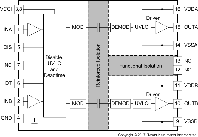
输入侧通过一个 5.7kVRMS 增强型隔离层与两个输出驱动器隔离,共模瞬态抗扰度 (CMTI) 的最小值为 100V/ns。两个二次侧驱动器之间采用内部功能隔离,支持高达 1500 VDC 的工作电压。
每个驱动器可配置为两个低侧驱动器、两个高侧驱动器或一个死区时间 (DT) 可编程的半桥驱动器。禁用引脚可同时关断两个输出,在保持开路或接地时允许器件正常运行。作为一种失效防护机制,初级侧逻辑故障会强制两个输出为低电平。
每个器件接受高达 25V 的 VDD 电源电压。凭借 3V 至 18V 的宽输入电压 VCCI 范围,该驱动器非常适合连接模拟和数字控制器。所有电源电压引脚都具有欠压锁定 (UVLO) 保护功能。
凭借上述所有高级 功能,UCC21520-Q1 可以实现高效率、高功率密度和稳健性。
器件比较(1)
| 器件编号 | 封装 | UVLO 级别 |
|---|---|---|
| UCC21520-Q1 | DW SOIC (16) | 8V |
| UCC21520A-Q1 | DW SOIC (16) | 5V |
- 如需了解所有可用封装,请参阅数据表末尾的可订购产品附录。
功能方框图
