ZHCSFS3A December 2016 – February 2019 UC1843A-SP
PRODUCTION DATA.
9.2.2 Detailed Design Procedure
See Table 2 for component values.
Table 2. Components(1)
| COMPONENT | VALUE |
|---|---|
| R1 | 5 Ω, 1 W |
| R2 | 56 kΩ, 2 W |
| R3 | 20 kΩ |
| R4 | 4.7 kΩ |
| R5 | 150 kΩ |
| R6 | 10 kΩ |
| R7 | 22 Ω |
| R8 | 1 kΩ |
| R9 | 68 Ω |
| R10 | 0.55 Ω, 1 W |
| R11 | 2.7 kΩ, 2 W |
| R12 | 4.7 kΩ, 2 W |
| R13 | 20 kΩ |
| C1 | 250 µF, 250 V |
| C2 | 100 µF, 25 V |
| C3 | 22 µF |
| C4 | 47 µF, 25 V |
| C5 | 0.1 µF |
| C6 | 0.0022 µF |
| C7 | 470 pF |
| C8 | 680 pF, 600 V |
| C9 | 3300 pF, 600 V |
| C10 | 4700 µF, 10 V |
| C11 | 4700 µF, 10 V |
| C12 | 2200 µF, 10 V |
| C13 | 2200 µF, 10 V |
| C14 | 100 pF |
| D2 | 1N3612 |
| D3 | 1N3612 |
| D4 | 1N3613 |
| D5 | 1N3613 |
| D6 | USD945 |
| D7 | UFS1002 |
| D8 | UES1002 |
| Q1 | UFN833 |
(1) See Figure 11 for reference.
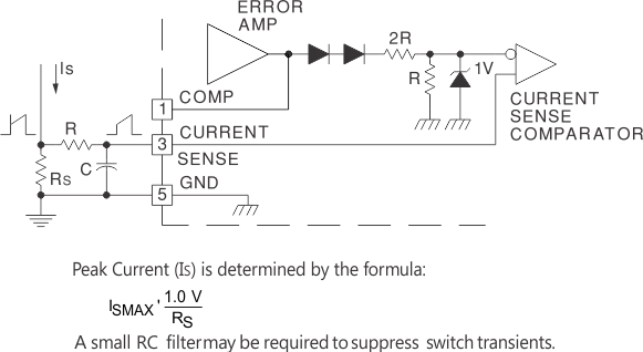
 Figure 12. Current-Sense Circuit
NOTE:
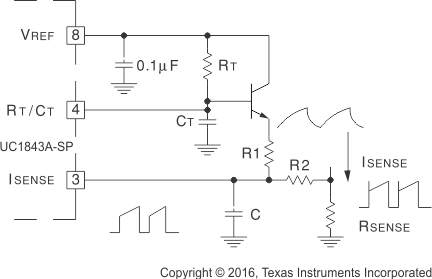
A fraction of the oscillator ramp can be resistively summed with the current sense signal to provide slope compensation for converters requiring duty cycles over 50%.Capacitor, C, forms a filter with R2 to suppress the leading edge switch spikes.
Figure 13. Slope Compensation