ZHCSK92E September 2019 – March 2022 TPS25840-Q1 , TPS25842-Q1
PRODUCTION DATA
- 1 特性
- 2 应用
- 3 说明
- 4 Revision History
- 5 说明(续)
- 6 Device Comparison Table
- 7 Pin Configuration and Functions
- 8 Specifications
- 9 Parameter Measurement Information
-
10Detailed Description
- 10.1 Overview
- 10.2 Functional Block Diagram
- 10.3
Feature Description
- 10.3.1 Buck Regulator
- 10.3.2 Enable/UVLO
- 10.3.3 Switching Frequency and Synchronization (RT/SYNC)
- 10.3.4 Spread-Spectrum Operation
- 10.3.5 VCC, VCC_UVLO
- 10.3.6 Minimum ON-time, Minimum OFF-time
- 10.3.7 Internal Compensation
- 10.3.8 Bootstrap Voltage (BOOT)
- 10.3.9 RSNS, RSET, RILIMIT and RIMON
- 10.3.10 Overcurrent and Short Circuit Protection
- 10.3.11 Overvoltage, IEC and Short-to-Battery Protection
- 10.3.12 Cable Compensation
- 10.3.13 USB Port Control
- 10.3.14 FAULT Response
- 10.3.15 USB Specification Overview
- 10.3.16 Device Power Pins (IN, CSN/OUT, and PGND)
- 10.3.17 Thermal Shutdown
- 10.4 Device Functional Modes
-
11Application and Implementation
- 11.1 Application Information
- 11.2
Typical Application
- 11.2.1 Design Requirements
- 11.2.2
Detailed Design Procedure
- 11.2.2.1 Output Voltage
- 11.2.2.2 Switching Frequency
- 11.2.2.3 Inductor Selection
- 11.2.2.4 Output Capacitor Selection
- 11.2.2.5 Input Capacitor Selection
- 11.2.2.6 Bootstrap Capacitor Selection
- 11.2.2.7 VCC Capacitor Selection
- 11.2.2.8 Enable and Under Voltage Lockout Set-Point
- 11.2.2.9 Current Limit Set-Point
- 11.2.2.10 Cable Compensation Set-Point
- 11.2.2.11 FAULT Resistor Selection
- 11.2.3 Application Curves
- 12Power Supply Recommendations
- 13Layout
- 14Device and Documentation Support
- 15Mechanical, Packaging, and Orderable Information
3 说明
TPS2584x-Q1 是 USB Type-A BC1.2 充电解决方案,其中包括一个同步直流/直流转换器。凭借电缆压降补偿,不管负载电流如何变化,Vbus 都保持恒定,确保即使在重负载期间也能以合适的电流和电压为连接的便携式设备充电。
TPS2584x-Q1 包括可实现 DP 和 DM 直通的高带宽模拟开关。
TPS25840-Q1 还在 VBUS、DM_IN 和 DP_IN 引脚上集成了电池短路保护。这些引脚可承受最高 18V 的电压。TPS25842-Q1 不支持数据线 (Dx) 对 VBAT 短路保护。
器件信息(1)
| 器件型号 | 封装 | 封装尺寸(标称值) |
|---|---|---|
TPS25840-Q1 | 超薄四方扁平无引线 (VQFN) (32) | 5.00mm x 5.00mm |
TPS25842-Q1 | 超薄四方扁平无引线 (VQFN) (32) | 5.00mm x 5.00mm |
(1) 如需了解所有可用封装,请参阅数据表末尾的可订购产品附录。
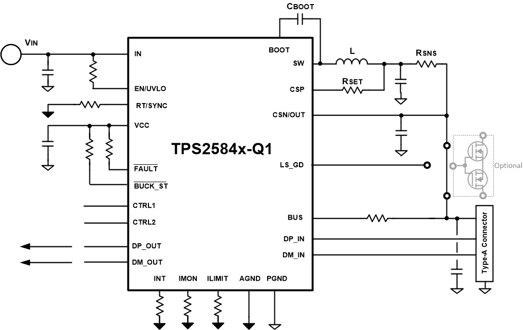
 TPS2584x-Q1 简化版原理图
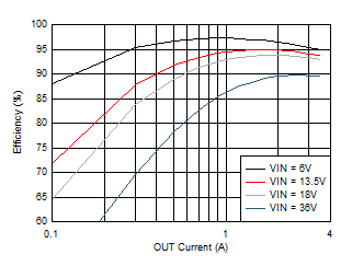
 降压效率与输出电流间的关系 (fsw = 400 kHz)