ZHCSH16C November   2017  – August 2019 TPS25820 , TPS25821

PRODUCTION DATA.  

  1. 特性
  2. 应用
  3. 说明
    1.     Device Images
      1.      简化原理图
  4. 修订历史记录
  5. Pin Configuration and Functions
    1.     Pin Functions
  6. Specifications
    1. 6.1 Absolute Maximum Ratings
    2. 6.2 ESD Ratings
    3. 6.3 Recommended Operating Conditions
    4. 6.4 Thermal Information
    5. 6.5 Electrical Characteristics
    6. 6.6 Switching Characteristics
    7. 6.7 Typical Characteristics
  7. Detailed Description
    1. 7.1 Overview
      1. 7.1.1 USB Type C Basic
      2. 7.1.2 Configuration Channel
      3. 7.1.3 Detecting a Connection
    2. 7.2 Functional Block Diagrams
    3. 7.3 Feature Description
      1. 7.3.1 Configuration Channel Pins CC1 and CC2
      2. 7.3.2 Current Capability Advertisement and VBUS Overload Protection
      3. 7.3.3 FAULT Response
      4. 7.3.4 Thermal Shutdown
      5. 7.3.5 REF
      6. 7.3.6 Plug Polarity Detection
      7. 7.3.7 Sink Attachment Indicator
      8. 7.3.8 Device Enable Control
      9. 7.3.9 Undervoltage Lockout (UVLO)
    4. 7.4 Device Functional Modes
  8. Application and Implementation
    1. 8.1 Application Information
    2. 8.2 Typical Applications
      1. 8.2.1 Type-C Source Port Implementation without BC 1.2 Support
        1. 8.2.1.1 Design Requirements
          1. 8.2.1.1.1 Input and Output Capacitance Considerations
          2. 8.2.1.1.2 System Level ESD Protection
        2. 8.2.1.2 Detailed Design Procedure
        3. 8.2.1.3 Application Curves
      2. 8.2.2 Type -C Source Port Implementation with BC 1.2 (DCP Mode) Support
        1. 8.2.2.1 Design Requirements
        2. 8.2.2.2 Detailed Design Procedure
        3. 8.2.2.3 Application Curves
      3. 8.2.3 Implementing a USB 3.1 Type-C Charging Port with the TPS25820
        1. 8.2.3.1 Design Requirements
        2. 8.2.3.2 Detailed Design Procedure
        3. 8.2.3.3 Application Curves
      4. 8.2.4 Implementing TPS25821 in USB Car Chargers
        1. 8.2.4.1 Design Requirements
        2. 8.2.4.2 Detailed Design Procedure
        3. 8.2.4.3 Application Curves
  9. Power Supply Recommendations
  10. 10Layout
    1. 10.1 Layout Guidelines
    2. 10.2 Layout Example
  11. 11器件和文档支持
    1. 11.1 器件支持
      1. 11.1.1 第三方产品免责声明
    2. 11.2 文档支持
      1. 11.2.1 相关文档
    3. 11.3 相关链接
    4. 11.4 接收文档更新通知
    5. 11.5 社区资源
    6. 11.6 商标
    7. 11.7 静电放电警告
    8. 11.8 Glossary
  12. 12机械、封装和可订购信息

封装选项

机械数据 (封装 | 引脚)
散热焊盘机械数据 (封装 | 引脚)
订购信息

Application Curves

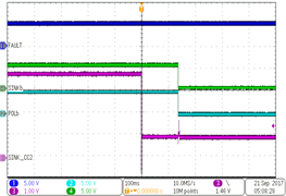
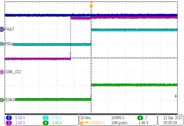
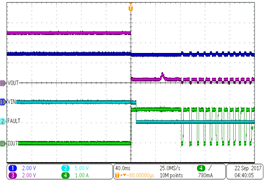
TPS25820 TPS25821 F13_snk_att_slvse24.png
Figure 13. Sink Attach Event
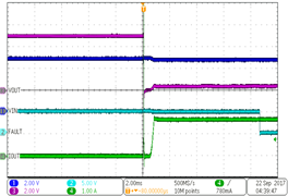
TPS25820 TPS25821 F15_o_shrt_evnt_slvse24.png
COUT = 6.8 µF, Short Output, IN=EN=5V, CC1=Rd, CC2 open
Figure 15. Out Short Event
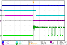
TPS25820 TPS25821 F17_scrwdrvr_slvse24.png
Figure 17. Screw Driver Short on VBUS
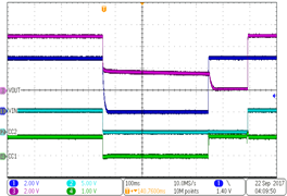
TPS25820 TPS25821 F14_snk_det_slvse24.png
Figure 14. Sink Detach Event
TPS25820 TPS25821 F16_e_o_shrt_evnt_slvse24.png
Figure 16. Extended Period OUT Short Event
TPS25820 TPS25821 F18_brnout_slvse24.png
VIN: 5V ≥ 0V - 5V;1V/ms,365 ms wait,CC1 = Rd,CC2 = open
Figure 18. Brownout Test