ZHCSCG6A May 2014 – December 2014 TPS2513A-Q1 , TPS2514A-Q1
PRODUCTION DATA.
6 Pin Configuration and Functions
TPS2513A-Q1
DBV (SOT23-6)
(TOP VIEW)
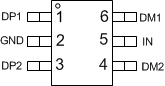
Pin Functions, TPS2513A-Q1
| NO. | NAME | TYPE(1) | DESCRIPTION |
|---|---|---|---|
| 1 | DP1 | I/O | Connected to the D+ line of USB connector, provide the correct voltage with attached portable equipment for DCP detection. |
| 2 | GND | G | Ground connection |
| 3 | DP2 | I/O | Connected to the D+ line of USB connector, provide the correct voltage with attached portable equipment for DCP detection. |
| 4 | DM2 | I/O | Connected to the D– line of USB connector, provide the correct voltage with attached portable equipment for DCP detection. |
| 5 | IN | P | Power supply. Connect a ceramic capacitor with a value of 0.1-μF or greater from the IN pin to GND as close to the device as possible. |
| 6 | DM1 | I/O | Connected to the D– line of USB connector, provide the correct voltage with attached portable equipment for DCP detection. |
(1) G = Ground, I = Input, O = Output, P = Power
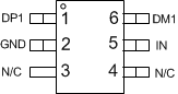
Pin Functions, TPS2514A-Q1
| NO. | NAME | TYPE(1) | DESCRIPTION |
|---|---|---|---|
| 1 | DP1 | I/O | Connected to the D+ line of USB connector, provide the correct voltage with attached portable equipment for DCP detection. |
| 2 | GND | G | Ground connection |
| 3 | N/C | – | No connect pin, can be grounded or left floating. |
| 4 | N/C | – | No connect pin, can be grounded or left floating |
| 5 | IN | P | Power supply. Connect a ceramic capacitor with a value of 0.1-μF or greater from the IN pin to GND as close to the device as possible. |
| 6 | DM1 | I/O | Connected to the D– line of USB connector, provide the correct voltage with attached portable equipment for DCP detection. |
(1) G = Ground, I = Input, O = Output, P = Power