ZHCSQI5I August 1990 – October 2022 SN55LBC176 , SN65LBC176 , SN75LBC176
PRODUCTION DATA
- 1 特性
- 2 说明
- 3 Revision History
- 4 说明(续)
- 5 Pin Configuration and Functions
-
6 Specifications
- 6.1 Absolute Maximum Ratings
- 6.2 Recommended Operating Conditions
- 6.3 Thermal Information: SN55LBC176
- 6.4 Thermal Information: SN65LBC176, SN75LBC176
- 6.5 Dissipation Ratings
- 6.6 Driver Electrical Characteristics
- 6.7 Driver Switching Characteristics
- 6.8 Receiver Electrical Characteristics
- 6.9 Receiver Switching Characteristics
- 7 Parameter Measurement Information
- 8 Detailed Description
- 9 Device and Documentation Support
- 10Mechanical, Packaging, and Orderable Information
2 说明
SN55LBC176、SN65LBC176、SN65LBC176Q 和 SN75LBC176 差分总线收发器是单片集成电路,旨在用于多点总线传输线路上的双向数据通信。这些器件专为平衡传输线路而设计,符合 ANSI 标准
TIA/EIA−485−A (RS-485) 和 ISO 8482:1987(E)。
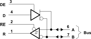
SN55LBC176、SN65LBC176、SN65LBC176Q 和 SN75LBC176 器件整合了一个三态差分线路驱动器和一个差分输入线路接收器,两者均采用 5V 单电源供电。驱动器和接收器分别具有高电平有效和低电平有效使能端,它们可以在外部连接在一起以用作方向控制。驱动器差分输出端和接收器差分输入端在内部连接以形成差分输入/输出 (I/O) 总线端口,该端口用于在禁用驱动器或 VCC = 0 时为总线提供最小负载。该端口具有较宽的正负共模电压范围,使得该器件适用于合用线应用。可以通过禁用驱动器和接收器来实现较低的器件电源电流。
封装信息
| 器件型号 | 封装(1) | 封装尺寸(标称值) |
|---|---|---|
| SN55LBC176 | LCCC (20) | 8.89 mm x 8.89 mm |
| CDIP (8) | 9.60 mm x 6.67 mm | |
| SN65LBC176 | SOIC (8) | 4.90mm x 3.91mm |
| PDIP (8) | 9.81mm x 6.35mm | |
| SN75LBC176 | SOIC (8) | 4.90mm x 3.91mm |
| PDIP (8) | 9.81mm x 6.35mm |
(1) 如需了解所有可用封装,请参阅数据表末尾的可订购产品附录。
 图 2-1 逻辑图(正逻辑)