ZHCSCY7C July   2014  – November 2017 OPT3001

PRODUCTION DATA.  

  1. 特性
  2. 应用
  3. 说明
  4. 修订历史记录
  5. Pin Configuration and Functions
  6. Specifications
    1. 6.1 Absolute Maximum Ratings
    2. 6.2 ESD Ratings
    3. 6.3 Recommended Operating Conditions
    4. 6.4 Thermal Information
    5. 6.5 Electrical Characteristics
    6. 6.6 Timing Requirements
    7. 6.7 Typical Characteristics
  7. Detailed Description
    1. 7.1 Overview
    2. 7.2 Functional Block Diagram
    3. 7.3 Feature Description
      1. 7.3.1 Human Eye Matching
      2. 7.3.2 Automatic Full-Scale Range Setting
      3. 7.3.3 Interrupt Operation, INT Pin, and Interrupt Reporting Mechanisms
      4. 7.3.4 I2C Bus Overview
        1. 7.3.4.1 Serial Bus Address
        2. 7.3.4.2 Serial Interface
    4. 7.4 Device Functional Modes
      1. 7.4.1 Automatic Full-Scale Setting Mode
      2. 7.4.2 Interrupt Reporting Mechanism Modes
        1. 7.4.2.1 Latched Window-Style Comparison Mode
        2. 7.4.2.2 Transparent Hysteresis-Style Comparison Mode
        3. 7.4.2.3 End-of-Conversion Mode
        4. 7.4.2.4 End-of-Conversion and Transparent Hysteresis-Style Comparison Mode
    5. 7.5 Programming
      1. 7.5.1 Writing and Reading
        1. 7.5.1.1 High-Speed I2C Mode
        2. 7.5.1.2 General-Call Reset Command
        3. 7.5.1.3 SMBus Alert Response
    6. 7.6 Register Maps
      1. 7.6.1 Internal Registers
        1. 7.6.1.1 Register Descriptions
          1. 7.6.1.1.1 Result Register (offset = 00h)
          2. 7.6.1.1.2 Configuration Register (offset = 01h) [reset = C810h]
          3. 7.6.1.1.3 Low-Limit Register (offset = 02h) [reset = C0000h]
          4. 7.6.1.1.4 High-Limit Register (offset = 03h) [reset = BFFFh]
          5. 7.6.1.1.5 Manufacturer ID Register (offset = 7Eh) [reset = 5449h]
          6. 7.6.1.1.6 Device ID Register (offset = 7Fh) [reset = 3001h]
  8. Application and Implementation
    1. 8.1 Application Information
      1. 8.1.1 Electrical Interface
      2. 8.1.2 Optical Interface
    2. 8.2 Typical Application
      1. 8.2.1 Design Requirements
      2. 8.2.2 Detailed Design Procedure
        1. 8.2.2.1 Optomechanical Design
        2. 8.2.2.2 Dark Window Selection and Compensation
      3. 8.2.3 Application Curves
    3. 8.3 Do's and Don'ts
  9. Power-Supply Recommendations
  10. 10Layout
    1. 10.1 Layout Guidelines
    2. 10.2 Layout Example
  11. 11器件和文档支持
    1. 11.1 文档支持
      1. 11.1.1 相关文档
    2. 11.2 接收文档更新通知
    3. 11.3 社区资源
    4. 11.4 商标
    5. 11.5 静电放电警告
    6. 11.6 Glossary
  12. 12机械、封装和可订购信息
    1. 12.1 关于焊接和处理的相关建议
    2. 12.2 DNP (S-PDSO-N6) 机械制图

封装选项

机械数据 (封装 | 引脚)
散热焊盘机械数据 (封装 | 引脚)
订购信息

机械、封装和可订购信息

以下页中包括机械封装、封装和可订购信息。这些信息是针对指定器件可提供的最新数据。数据如有变更,恕不另行通知和修订此文档。如欲获取此数据表的浏览器版本,请参阅左侧的导航。

关于焊接和处理的相关建议

OPT3001 通过 JEDEC JSTD-020 认证,适用于三种回流焊操作。

请注意:温度过高会导致器件褪色并影响光学性能。

有关焊接热规范和其他详细信息,请参见应用报告《QFN/SON PCB 连接》(SLUA271)。如果必须从 PCB 上移除 OPT3001,请拆下此器件后不再重新连接。

处理 OPT3001 时需要像处理大多数光学器件那样谨慎操作,确保光学表面保持洁净无损伤。更多详细建议,请参见Do's and Don'ts部分。为获得最优光学性能,完成焊接后必须清理焊剂和任何其他碎屑。

DNP (S-PDSO-N6) 机械制图

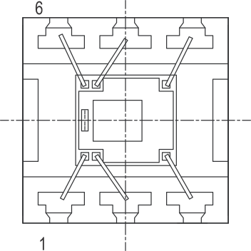
OPT3001 pin1_sbos681.gif Figure 36. 引脚 1 的封装方向视觉基准
(顶视图)
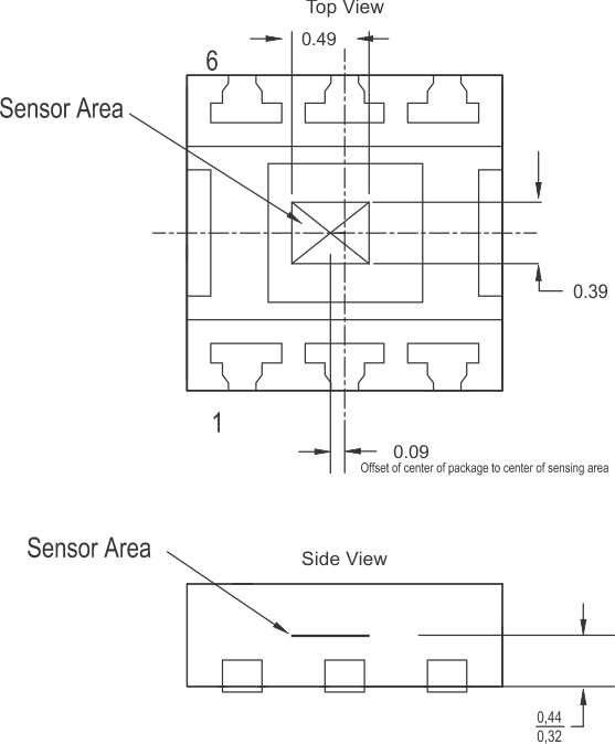
OPT3001 sensor_location_sbos681.gif Figure 37. 显示感测区域位置的机械制图
(顶视图和侧视图)