ZHCSJ01B January 2019 – August 2019 OPA1671
PRODUCTION DATA.
7.3.4 EMI Susceptibility and Input Filtering
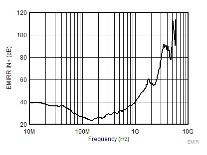
Operational amplifiers vary in susceptibility to EMI. If conducted EMI enters the operational amplifier, the dc offset at the amplifier output can shift from its nominal value when EMI is present. This shift is a result of signal rectification associated with the internal semiconductor junctions. Although all operational amplifier pin functions can be affected by EMI, the input pins are likely to be the most susceptible. The OPA1671 operational amplifier incorporates an internal input low-pass filter that reduces the amplifier response to EMI. Both common-mode and differential-mode filtering are provided by the input filter. The filter is designed for a cutoff frequency of approximately 20 MHz (–3 dB), with a rolloff of 20 dB per decade.
 Figure 31. OPA1671 EMIRR vs Frequency
 Table 1. OPA1671 EMIRR IN+ for Frequencies of Interest
| FREQUENCY | APPLICATION OR ALLOCATION | EMIRR IN+ |
|---|---|---|
| 400 MHz | Mobile radio, mobile satellite, space operation, weather, radar, ultra-high frequency (UHF) applications | 30 dB |
| 900 MHz | Global system for mobile communications (GSM) applications, radio communication, navigation, GPS (to 1.6 GHz), GSM, aeronautical mobile, UHF applications | 38 dB |
| 1.8 GHz | GSM applications, mobile personal communications, broadband, satellite, L-band (1 GHz to 2 GHz) | 60 dB |
| 2.4 GHz | 802.11b, 802.11g, 802.11n, Bluetooth®, mobile personal communications, industrial, scientific and medical (ISM) radio band, amateur radio and satellite, S-band (2 GHz to 4 GHz) | 59 dB |
| 3.6 GHz | Radiolocation, aero communication and navigation, satellite, mobile, S-band | 90 dB |
| 5 GHz | 802.11a, 802.11n, aero communication and navigation, mobile communication, space and satellite operation, C-band (4 GHz to 8 GHz) | 100 dB |