SNOSD61 June 2017 LMC6482-MIL
PRODUCTION DATA.
- 1 Features
- 2 Applications
- 3 Description
- 4 Pin Configuration and Functions
- 5 Specifications
- 6 Detailed Description
- 7 Application and Implementation
- 8 Power Supply Recommendations
- 9 Layout
- 10Device and Documentation Support
- 11Mechanical, Packaging, and Orderable Information
7 Application and Implementation
NOTE
Information in the following applications sections is not part of the TI component specification, and TI does not warrant its accuracy or completeness. TI’s customers are responsible for determining suitability of components for their purposes. Customers should validate and test their design implementation to confirm system functionality.
7.1 Application Information
7.1.1 Upgrading Applications
The LMC6484 quads and LMC6482-MIL duals have industry-standard pin outs to retrofit existing applications. System performance can be greatly increased by the features of the LMC6482-MIL. The key benefit of designing in the LMC6482-MIL is increased linear signal range. Most op-amps have limited input common-mode ranges. Signals that exceed this range generate a nonlinear output response that persists long after the input signal returns to the common-mode range.
Linear signal range is vital in applications such as filters where signal peaking can exceed input common-mode ranges resulting in output phase inversion or severe distortion.
7.1.2 Data Acquisition Systems
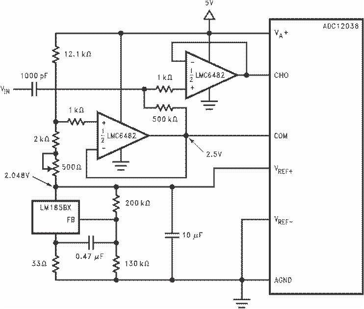
Low power, single supply data acquisition system solutions are provided by buffering the ADC12038 with the LMC6482-MIL (Figure 56). Capable of using the full supply range, the LMC6482-MIL does not require input signals to be scaled down to meet limited common-mode voltage ranges. The LMC4282 CMRR of 82 dB maintains integral linearity of a 12-bit data acquisition system to ±0.325 LSB. Other rail-to-rail input amplifiers with only 50 dB of CMRR will degrade the accuracy of the data acquisition system to only 8 bits.
7.1.3 Instrumentation Circuits
The LMC6482-MIL has the high input impedance, large common-mode range and high CMRR needed for designing instrumentation circuits. Instrumentation circuits designed with the LMC6482-MIL can reject a larger range of common-mode signals than most in-amps. This makes instrumentation circuits designed with the LMC6482-MIL an excellent choice of noisy or industrial environments. Other applications that benefit from these features include analytic medical instruments, magnetic field detectors, gas detectors, and silicon-based transducers.
A small valued potentiometer is used in series with Rg to set the differential gain of the 3-op-amp instrumentation circuit in Figure 57. This combination is used instead of one large valued potentiometer to increase gain trim accuracy and reduce error due to vibration.
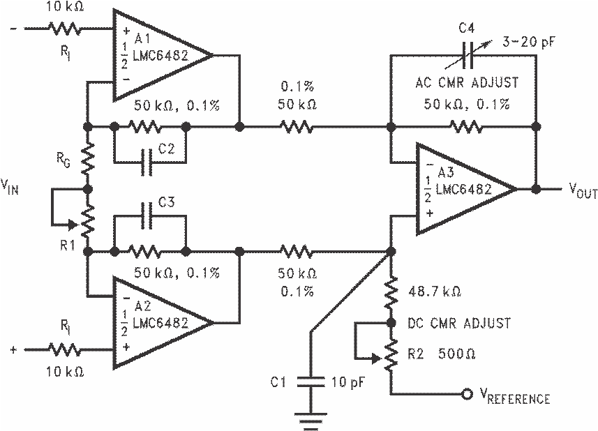 Figure 57. Low Power 3-Op-Amp Instrumentation Amplifier
A 2-op-amp instrumentation amplifier designed for a gain of 100 is shown in Figure 58. Low sensitivity trimming is made for offset voltage, CMRR, and gain. Low cost and low power consumption are the main advantages of this 2-op-amp circuit.
Higher frequency and larger common-mode range applications are best facilitated by a 3-op-amp instrumentation amplifier.
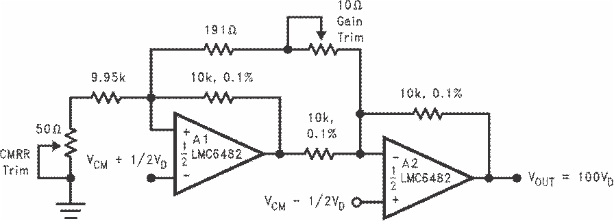 Figure 58. Low-Power Two-Op-Amp Instrumentation Amplifier
7.1.4 Spice Macromodel
A spice macromodel is available for the LMC6482-MIL. This model includes accurate simulation of the following:
- Input common-mode voltage range
- Frequency and transient response
- GBW dependence on loading conditions
- Quiescent and dynamic supply current
- Output swing dependence on loading conditions
Many more characteristics are listed on the macromodel disk.
Contact your local TI sales office to obtain an operational amplifier spice model library disk.
7.2 Typical Applications
7.2.1 3-V Single Supply Buffer Circuit
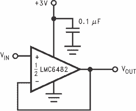 Figure 59. 3-V Single Supply Buffer Circuit
7.2.1.1 Design Requirements
For best performance, ensure that the input voltage swing is between V+ and V-.
Ensure that the input does not exceed the common-mode input range.
To reduce the risk of destabilizing the output, use resistive isolation on the output when driving capacitive loads (see the Detailed Design Procedure section).
When large feedback resistors are used, it may be necessary to compensate for parasitic capacitance on the input. See the Detailed Design Procedure section.
7.2.1.2 Detailed Design Procedure
7.2.1.2.1 Capacitive Load Compensation
Capacitive load compensation can be accomplished using resistive isolation as shown in Figure 60. This simple technique is useful for isolating the capacitive inputs of multiplexers and A/D converters.
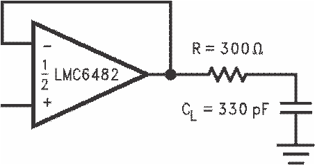 Figure 60. Resistive Isolation of a 330-pF Capacitive Load
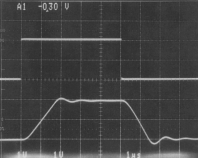 Figure 61. Pulse Response of the LMC6482-MIL Circuit in Figure 60
7.2.1.2.1.1 Capacitive Load Tolerance
The LMC6482-MIL can typically directly drive a 100-pF load with VS = 15 V at unity gain without oscillating. The unity gain follower is the most sensitive configuration. Direct capacitive loading reduces the phase margin of op-amps. The combination of the output impedance of the op-amp and the capacitive load induces phase lag. This results in either an underdamped pulse response or oscillation.
Improved frequency response is achieved by indirectly driving capacitive loads, as shown in Figure 62.
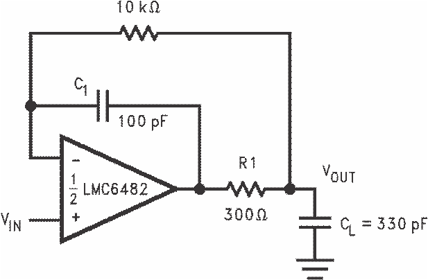
R1 and C1 serve to counteract the loss of phase margin by feeding forward the high-frequency component of the output signal back to the amplifiers inverting input, thereby preserving phase margin in the overall feedback loop. The values of R1 and C1 are experimentally determined for the desired pulse response. The resulting pulse response is shown in Figure 63.
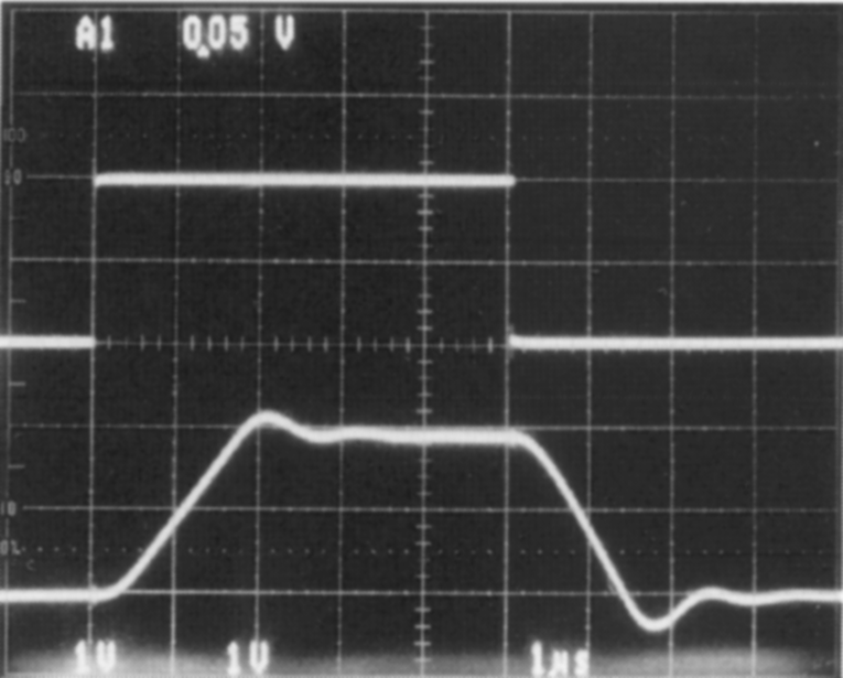 Figure 63. Pulse Response of
LMC6482-MIL Circuit in Figure 62
7.2.1.2.1.2 Compensating for Input Capacitance
It is quite common to use large values of feedback resistance with amplifiers that have ultralow input current, like the LMC6482-MIL. Large feedback resistors can react with small values of input capacitance due to transducers, photo diodes, and circuits board parasitics to reduce phase margins.
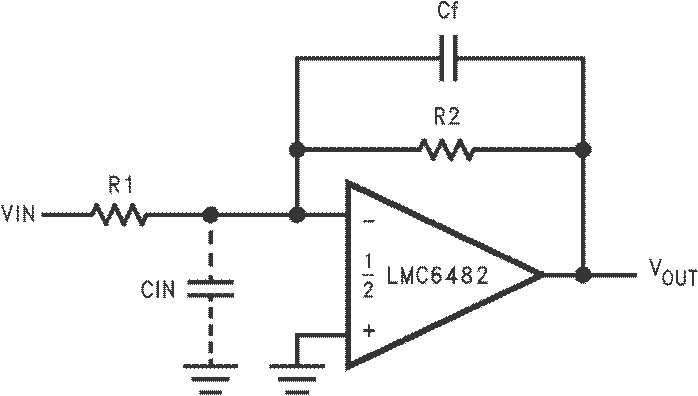 Figure 64. Canceling the Effect of Input Capacitance
The effect of input capacitance can be compensated for by adding a feedback capacitor. The feedback capacitor (as in Figure 64), Cf, is first estimated by:

or
which typically provides significant overcompensation.
Printed-circuit-board stray capacitance may be larger or smaller than that of a bread-board, so the actual optimum value for Cf may be different. The values of Cf should be checked on the actual circuit. (Refer to the LMC660 quad CMOS amplifier data sheet for a more detailed discussion.)
7.2.1.2.1.3 Offset Voltage Adjustment
Offset voltage adjustment circuits are illustrated in Figure 65 and Figure 66. Large value resistances and potentiometers are used to reduce power consumption while providing typically ±2.5 mV of adjustment range, referred to the input, for both configurations with VS = ±5 V.
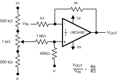 Figure 65. Inverting Configuration Offset Voltage Adjustment
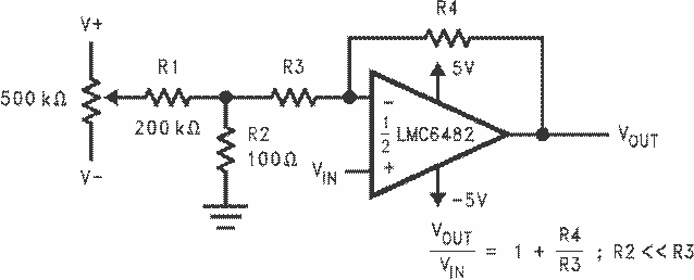 Figure 66. Noninverting Configuration Offset Voltage Adjustment
7.2.1.3 Application Curves
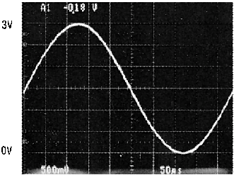 Figure 67. Rail-To-Rail Input
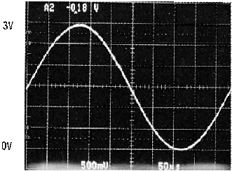 Figure 68. Rail-To-Rail Output
7.2.2 Typical Single-Supply Applications
The circuit in Figure 69 uses a single supply to half-wave rectify a sinusoid centered about ground. RI limits current into the amplifier caused by the input voltage exceeding the supply voltage. Full-wave rectification is provided by the circuit in Figure 71.
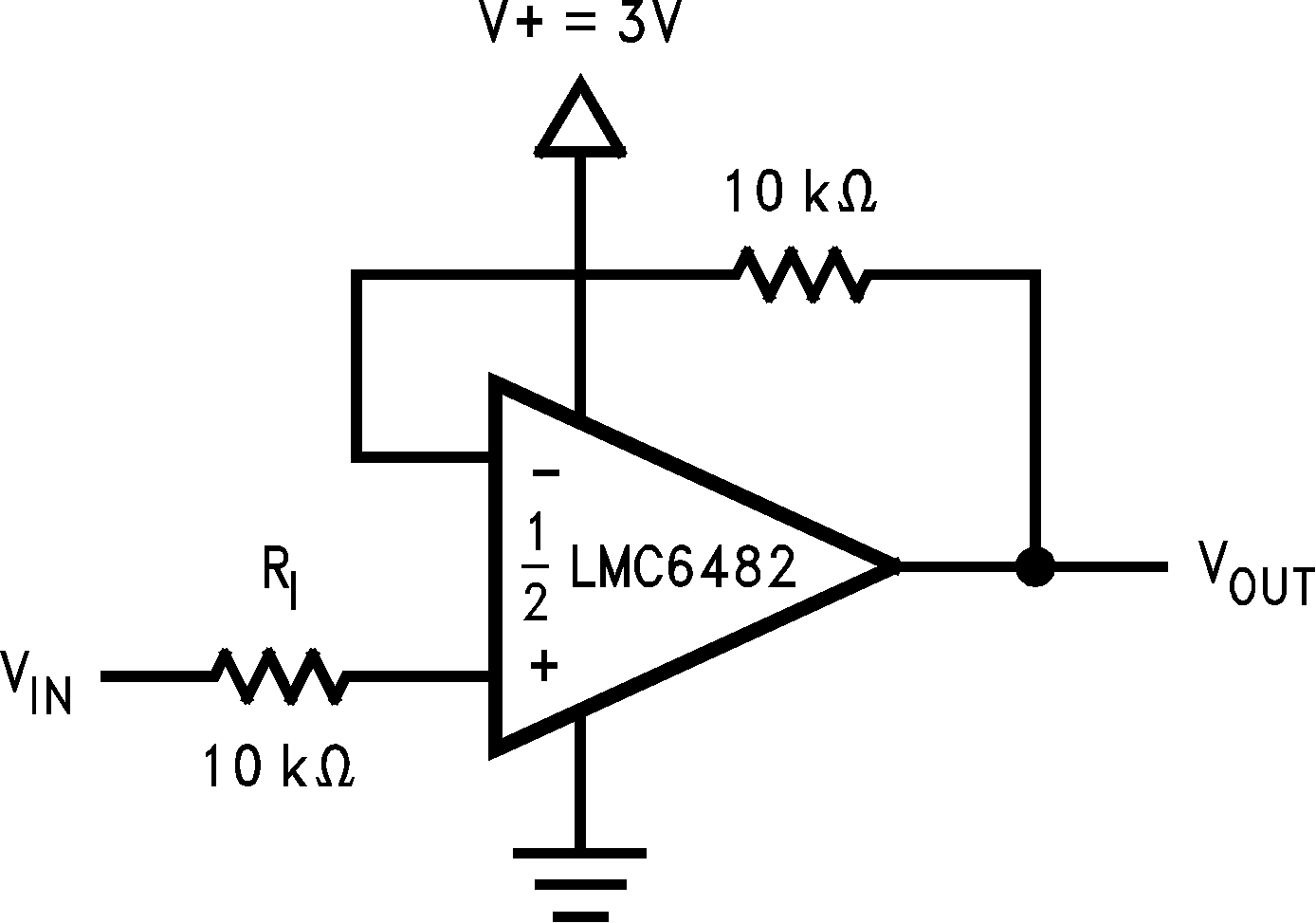 Figure 69. Half-Wave Rectifier With Input Current Protection (RI)
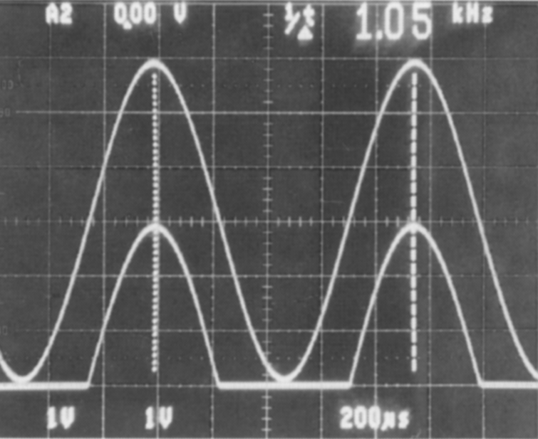 Figure 70. Half-Wave Rectifier Waveform
In Figure 75 dielectric absorption and leakage is minimized by using a polystyrene or polyethylene hold capacitor. The droop rate is primarily determined by the value of CH and diode leakage current. The ultralow input current of the LMC6482-MIL has a negligible effect on droop.
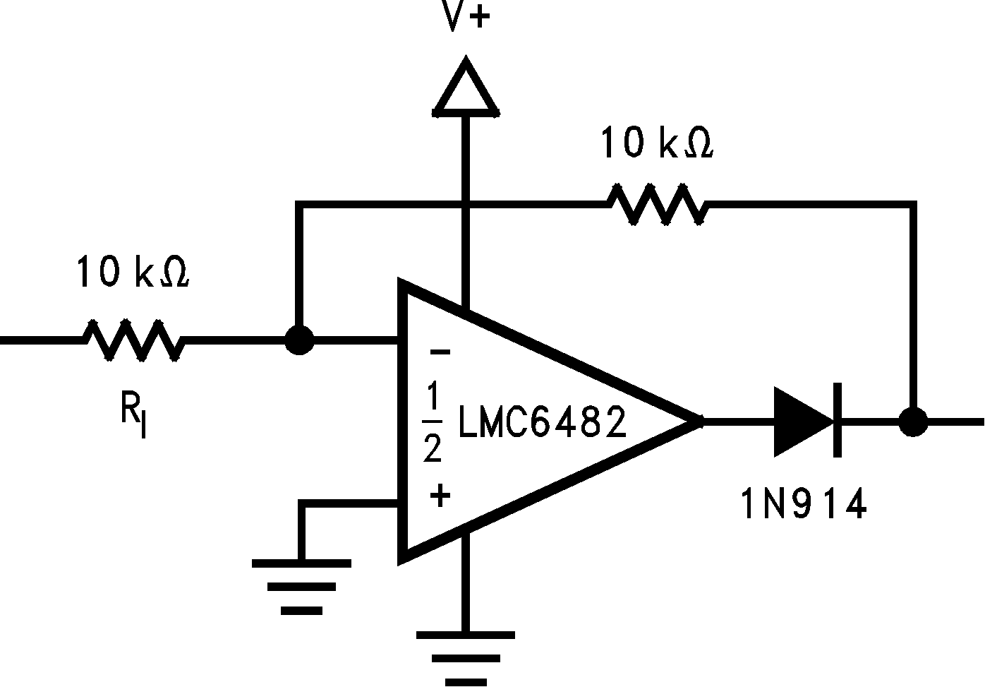 Figure 71. Full-Wave Rectifier With Input Current Protection (RI)
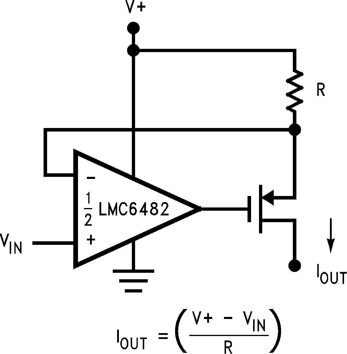 Figure 73. Large Compliance Range Current Source
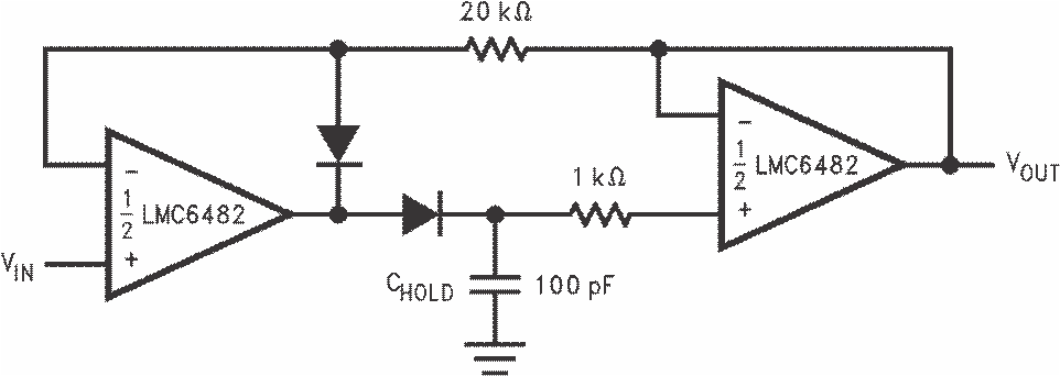 Figure 75. Low-Voltage Peak Detector With Rail-To-Rail Peak Capture Range
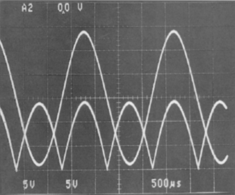 Figure 72. Full-Wave Rectifier Waveform
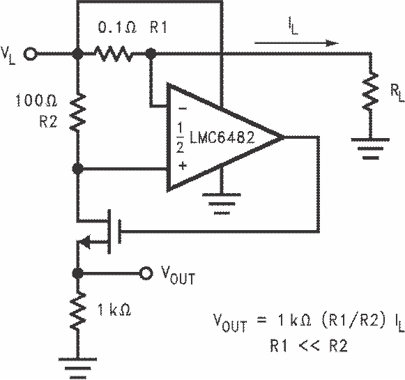 Figure 74. Positive Supply Current Sense
The high CMRR (82 dB) of the LMC6482-MIL allows excellent accuracy throughout the rail-to-rail dynamic capture range of the circuit.
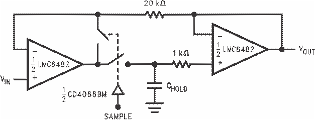 Figure 76. Rail-To-Rail Sample and Hold
The low-pass filter circuit in Figure 77 can be used as an anti-aliasing filter with the same voltage supply as the A/D converter.
Filter designs can also take advantage of the LMC6482-MIL ultralow input current. The ultralow input current yields negligible offset error even when large value resistors are used. This in turn allows the use of smaller valued capacitors which take less board space and cost less.

 Figure 77. Rail-To-Rail Single Supply Low Pass Filter