SNIS141F October 2005 – October 2015 LM73
PRODUCTION DATA.
- 1 Features
- 2 Applications
- 3 Description
- 4 Revision History
- 5 Pin Configuration and Functions
-
6 Specifications
- 6.1 Absolute Maximum Ratings
- 6.2 ESD Ratings
- 6.3 Recommended Operating Conditions
- 6.4 Thermal Information
- 6.5 Temperature-to-Digital Converter Characteristics
- 6.6 Logic Electrical Characteristics- Digital DC Characteristics
- 6.7 Logic Electrical Characteristics- SMBus Digital Switching Characteristics
- 6.8 Typical Characteristics
- 7 Detailed Description
- 8 Application and Implementation
- 9 Power Supply Recommendations
- 10Layout
- 11Device and Documentation Support
- 12Mechanical, Packaging, and Orderable Information
10 Layout
10.1 Layout Guidelines
To achieve the expected results when measuring temperature with an integrated circuit temperature sensor like the LM73, it is important to understand that the sensor measures its own die temperature. For the LM73, the best thermal path between the die and the outside world is through the LM73's pins. In the SOT-23 package, all the pins on the LM73 will have an equal effect on the die temperature. Because the pins represent a good thermal path to the LM73 die, the LM73 will provide an accurate measurement of the temperature of the printed circuit board on which it is mounted.
10.2 Layout Example
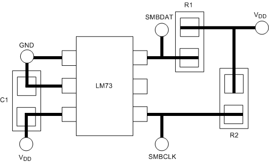
 Figure 16. PBC Layout