ZHCSD19A September 2014 – October 2015 DLP9000
PRODUCTION DATA.
- 1 特性
- 2 应用
- 3 说明
- 4 修订历史记录
- 5 Description (continued)
- 6 Pin Configuration and Functions
-
7 Specifications
- 7.1 Absolute Maximum Ratings
- 7.2 Storage Conditions
- 7.3 ESD Ratings
- 7.4 Recommended Operating Conditions
- 7.5 Thermal Information
- 7.6 Electrical Characteristics
- 7.7 Timing Requirements
- 7.8 Capacitance at Recommended Operating Conditions
- 7.9 Typical Characteristics
- 7.10 System Mounting Interface Loads
- 7.11 Micromirror Array Physical Characteristics
- 7.12 Micromirror Array Optical Characteristics
- 7.13 Optical and System Image Quality
- 7.14 Window Characteristics
- 7.15 Chipset Component Usage Specification
- 8 Parameter Measurement Information
- 9 Detailed Description
- 10Application and Implementation
- 11Power Supply Recommendations
- 12Layout
- 13器件和文档支持
- 14机械、封装和可订购信息
13 器件和文档支持
13.1 器件支持
13.1.1 器件处理
DMD 上的所有外部信号均不受静电放电的损害,经测试符合 JESD22-A114-B 静电放电 (ESD) 敏感度测试人体模型 (HBM)。
Table 10. DMD ESD 保护限值
| 封装引脚类型 | 电压(最大值) | 单位 |
|---|---|---|
| 输入 | 2000 | V |
| 输出 | 2000 | V |
| VCC | 2000 | V |
| VCCI | 2000 | V |
| VOFFSET | 2000 | V |
| VBIAS | 2000 | V |
| VRESET | 2000 | V |
| 所有 MBRST | 2000 | V |
所有 CMOS 器件均需遵循适当的静电放电 (ESD) 处理程序。请参见图纸 2504641 DMD 处理规范,了解关于对 DMD 实施 ESD 保护以及保护 DMD 玻璃和电触点的预防措施。请参见图纸 2504640 DMD 玻璃清洁程序,掌握 DMD 玻璃的正确清洁方式,避免损坏玻璃表面上的抗反射涂层。
13.1.2 器件命名规则
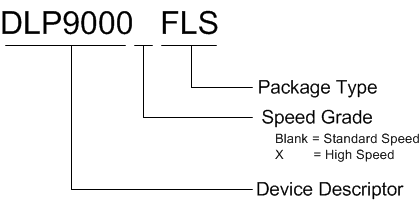
Figure 21 提供了读取任一 DLP 器件完整器件名称的图例。
Table 11. 封装专用信息
| 封装类型 | 替代名称 |
|---|---|
| FLS | LCCC |
 Figure 21. 器件命名规则
13.1.3 器件标记
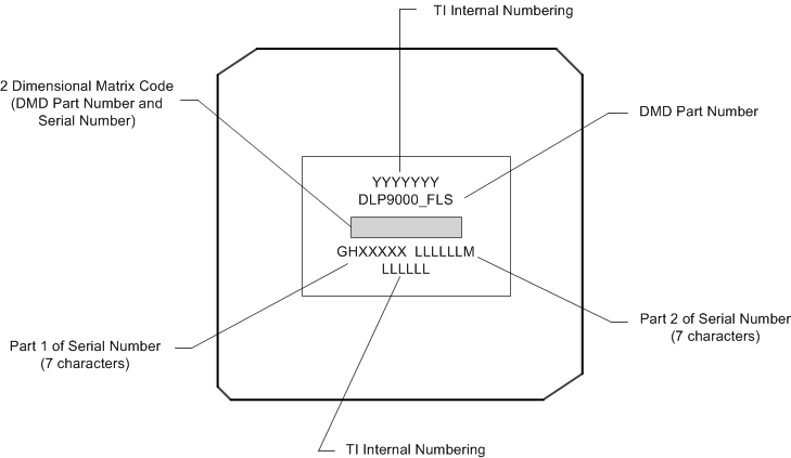
器件标记将包括可读信息和一个二维矩阵码。Figure 22 中显示了可读信息。二维矩阵码是一个字母数字字符串,其中包含 DMD 部件号、序列号的第 1 部分和序列号的第 2 部分。DMD 序列号(第 1 部分)的首字符为制造年份。DMD 序列号(第 1 部分)的第二个字符为制造月份。DMD 序列号(第 2 部分)的最后一个字符为偏置电压二进制字母。
 Figure 22. DMD 标记
13.2 文档支持
13.3 社区资源
The following links connect to TI community resources. Linked contents are provided "AS IS" by the respective contributors. They do not constitute TI specifications and do not necessarily reflect TI's views; see TI's Terms of Use.
-
TI E2E™ Online Community TI's Engineer-to-Engineer (E2E) Community. Created to foster collaboration among engineers. At e2e.ti.com, you can ask questions, share knowledge, explore ideas and help solve problems with fellow engineers.
-
Design Support TI's Design Support Quickly find helpful E2E forums along with design support tools and contact information for technical support.
13.4 商标
E2E is a trademark of Texas Instruments.
All other trademarks are the property of their respective owners.
13.5 静电放电警告

这些装置包含有限的内置 ESD 保护。 存储或装卸时,应将导线一起截短或将装置放置于导电泡棉中,以防止 MOS 门极遭受静电损伤。
13.6 Glossary
SLYZ022 — TI Glossary.
This glossary lists and explains terms, acronyms, and definitions.