CD4541B
- Low Symmetrical Output Resistance, Typically 100
 at VDD = 15V
 - Built-In Low-Power RC Oscillator
- Oscillator Frequency Range . . . DC to 100kHz
- External Clock (Applied to Pin 3) can be Used Instead of Oscillator
- Operates as 2 N Frequency Divider or as a Single-Transition Timer
- Q/Q\ Select Provides Output Logic Level Flexibility
- AUTO or MASTER RESET Disables Oscillator During Reset to Reduce Power Dissipation
- Operates With Very Slow Clock Rise and Fall Times
- Capable of Driving Six Low Power TTL Loads, Three Low-Power Schottky Loads, or Six HTL Loads Over the Rated Temperature Range
- Symmetrical Output Characteristics
- 100% Tested for Quiescent Current at 20V
- 5V, 10V, and 15V Parametric Ratings
- Meets All Requirements of JEDEC Standard No. 13B, "Standard Specifications for Description of ’B’ Series CMOS Devices"
Data sheet acquired from Harris Semiconductor
CD4541B programmable timer consists of a 16-stage binary counter, an oscillator that is controlled by external R-C components (2 resistors and a capacitor), an automatic power-on reset circuit, and output control logic. The counter increments on positive-edge clock transitions and can also be reset via the MASTER RESET input.
The output from this timer is the Q or Q\ output from the 8th, 10th, 13th, or 16th counter stage. The desired stage is chosen using time-select inputs A and B (see Frequency Select Table).
The output is available in either of two modes selectable via the MODE input, pin 10 (see Truth Table). When this MODE input is a logic "1", the output will be a continuous square wave having a frequency equal to the oscillator frequency divided by 2N. With the MODE input set to logic "0" and after a MASTER RESET is initiated, the output (assuming Q output has been selected) changes from a low to a high state after 2N-1 counts and remains in that state until another MASTER RESET pulse is applied or the MODE input is set to a logic "1".
Timing is initialized by setting the AUTO RESET input (pin 5) to logic "0" and turning power on. If pin 5 is set to logic "1", the AUTO RESET circuit is disabled and counting will not start until after a positive MASTER RESET pulse is applied and returns to a low level. The AUTO RESET consumes an appreciable amount of power and should not be used if low-power operation is desired. For reliable automatic power-on reset, VDD should be greater than 5V.
The RC oscillator, shown in Figure 2, oscillates with a frequency determined by the RC network and is calculated using:
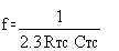 Where f is between 1kHz and 100kHz and RS and 2RTC.
技術文件
| 重要文件 | 類型 | 標題 | 格式選項 | 下載最新的英文版本 | 日期 | |
|---|---|---|---|---|---|---|
| * | 資料表 | CD4541B datasheet (Rev. E) | 2003/8/21 |
設計與開發
如需其他條款或必要資源,請按一下下方的任何標題以檢視詳細頁面 (如有)。
14-24-LOGIC-EVM — 適用於 14 針腳至 24 針腳 D、DB、DGV、DW、DYY、NS 和 PW 封裝的邏輯產品通用評估模組
14-24-LOGIC-EVM 評估模組 (EVM) 設計用於支援任何 14 針腳至 24 針腳 D、DW、DB、NS、PW、DYY 或 DGV 封裝的任何邏輯裝置。
| 封裝 | 針腳 | CAD 符號、佔位空間與 3D 模型 |
|---|---|---|
| PDIP (N) | 14 | Ultra Librarian |
| TSSOP (PW) | 14 | Ultra Librarian |
| SOIC (D) | 14 | Ultra Librarian |
| SOP (NS) | 14 | Ultra Librarian |