제품 상세 정보

Technology family CD4000 Bits (#) 1 Rating Catalog Operating temperature range (°C) -55 to 125
PDIP (N) 14 181.42 mm² (19.3 mm × 9.4 mm) TSSOP (PW) 14 32 mm² (5 mm × 6.4 mm) SOIC (D) 14 51.9 mm² (8.65 mm × 6 mm) SOP (NS) 14 79.56 mm² (10.2 mm × 7.8 mm)
  • Low Symmetrical Output Resistance, Typically 100 at VDD = 15V
  • Built-In Low-Power RC Oscillator
  • Oscillator Frequency Range . . . DC to 100kHz
  • External Clock (Applied to Pin 3) can be Used Instead of Oscillator
  • Operates as 2 N Frequency Divider or as a Single-Transition Timer
  • Q/Q\ Select Provides Output Logic Level Flexibility
  • AUTO or MASTER RESET Disables Oscillator During Reset to Reduce Power Dissipation
  • Operates With Very Slow Clock Rise and Fall Times
  • Capable of Driving Six Low Power TTL Loads, Three Low-Power Schottky Loads, or Six HTL Loads Over the Rated Temperature Range
  • Symmetrical Output Characteristics
  • 100% Tested for Quiescent Current at 20V
  • 5V, 10V, and 15V Parametric Ratings
  • Meets All Requirements of JEDEC Standard No. 13B, "Standard Specifications for Description of ’B’ Series CMOS Devices"

Data sheet acquired from Harris Semiconductor

  • Low Symmetrical Output Resistance, Typically 100 at VDD = 15V
  • Built-In Low-Power RC Oscillator
  • Oscillator Frequency Range . . . DC to 100kHz
  • External Clock (Applied to Pin 3) can be Used Instead of Oscillator
  • Operates as 2 N Frequency Divider or as a Single-Transition Timer
  • Q/Q\ Select Provides Output Logic Level Flexibility
  • AUTO or MASTER RESET Disables Oscillator During Reset to Reduce Power Dissipation
  • Operates With Very Slow Clock Rise and Fall Times
  • Capable of Driving Six Low Power TTL Loads, Three Low-Power Schottky Loads, or Six HTL Loads Over the Rated Temperature Range
  • Symmetrical Output Characteristics
  • 100% Tested for Quiescent Current at 20V
  • 5V, 10V, and 15V Parametric Ratings
  • Meets All Requirements of JEDEC Standard No. 13B, "Standard Specifications for Description of ’B’ Series CMOS Devices"

Data sheet acquired from Harris Semiconductor

CD4541B programmable timer consists of a 16-stage binary counter, an oscillator that is controlled by external R-C components (2 resistors and a capacitor), an automatic power-on reset circuit, and output control logic. The counter increments on positive-edge clock transitions and can also be reset via the MASTER RESET input.

The output from this timer is the Q or Q\ output from the 8th, 10th, 13th, or 16th counter stage. The desired stage is chosen using time-select inputs A and B (see Frequency Select Table).

The output is available in either of two modes selectable via the MODE input, pin 10 (see Truth Table). When this MODE input is a logic "1", the output will be a continuous square wave having a frequency equal to the oscillator frequency divided by 2N. With the MODE input set to logic "0" and after a MASTER RESET is initiated, the output (assuming Q output has been selected) changes from a low to a high state after 2N-1 counts and remains in that state until another MASTER RESET pulse is applied or the MODE input is set to a logic "1".

Timing is initialized by setting the AUTO RESET input (pin 5) to logic "0" and turning power on. If pin 5 is set to logic "1", the AUTO RESET circuit is disabled and counting will not start until after a positive MASTER RESET pulse is applied and returns to a low level. The AUTO RESET consumes an appreciable amount of power and should not be used if low-power operation is desired. For reliable automatic power-on reset, VDD should be greater than 5V.

The RC oscillator, shown in Figure 2, oscillates with a frequency determined by the RC network and is calculated using:
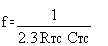
Where f is between 1kHz and 100kHz and RS and 2RTC.

CD4541B programmable timer consists of a 16-stage binary counter, an oscillator that is controlled by external R-C components (2 resistors and a capacitor), an automatic power-on reset circuit, and output control logic. The counter increments on positive-edge clock transitions and can also be reset via the MASTER RESET input.

The output from this timer is the Q or Q\ output from the 8th, 10th, 13th, or 16th counter stage. The desired stage is chosen using time-select inputs A and B (see Frequency Select Table).

The output is available in either of two modes selectable via the MODE input, pin 10 (see Truth Table). When this MODE input is a logic "1", the output will be a continuous square wave having a frequency equal to the oscillator frequency divided by 2N. With the MODE input set to logic "0" and after a MASTER RESET is initiated, the output (assuming Q output has been selected) changes from a low to a high state after 2N-1 counts and remains in that state until another MASTER RESET pulse is applied or the MODE input is set to a logic "1".

Timing is initialized by setting the AUTO RESET input (pin 5) to logic "0" and turning power on. If pin 5 is set to logic "1", the AUTO RESET circuit is disabled and counting will not start until after a positive MASTER RESET pulse is applied and returns to a low level. The AUTO RESET consumes an appreciable amount of power and should not be used if low-power operation is desired. For reliable automatic power-on reset, VDD should be greater than 5V.

The RC oscillator, shown in Figure 2, oscillates with a frequency determined by the RC network and is calculated using:

Where f is between 1kHz and 100kHz and RS and 2RTC.

다운로드 스크립트와 함께 비디오 보기 비디오

관심 가지실만한 유사 제품

open-in-new 대안 비교
비교 대상 장치와 유사한 기능.
TPL5010 활성 워치독 기능과 수동 리셋을 지원하는 나노 전력 시스템 타이머 Watchdog timer

기술 자료

검색된 결과가 없습니다. 검색어를 지우고 다시 시도하세요.
1개 모두 보기
상위 문서 유형 직함 형식 옵션 최신 영어 버전 다운로드 날짜
* 데이터 시트 CD4541B datasheet (Rev. E) 2003. 8. 21

설계 및 개발

추가 조건 또는 필수 리소스는 사용 가능한 경우 아래 제목을 클릭하여 세부 정보 페이지를 확인하세요.

평가 보드

14-24-LOGIC-EVM — 14핀~24핀 D, DB, DGV, DW, DYY, NS 및 PW 패키지용 로직 제품 일반 평가 모듈

14-24-LOGIC-EVM 평가 모듈(EVM)은 14핀~24핀 D, DW, DB, NS, PW, DYY 또는 DGV 패키지에 있는 모든 로직 장치를 지원하도록 설계되었습니다.

사용 설명서: PDF | HTML
지원되는 제품 및 하드웨어
재고 있음
제한:
??asset.out-of-stock-ti_ko_KR??
이용할 수 없음
패키지 CAD 기호, 풋프린트 및 3D 모델
PDIP (N) 14 Ultra Librarian
TSSOP (PW) 14 Ultra Librarian
SOIC (D) 14 Ultra Librarian
SOP (NS) 14 Ultra Librarian

주문 및 품질

지원 및 교육

TI 엔지니어의 기술 지원을 받을 수 있는 TI E2E™ 포럼

콘텐츠는 TI 및 커뮤니티 기고자에 의해 "있는 그대로" 제공되며 TI의 사양으로 간주되지 않습니다. 사용 약관을 참조하십시오.

품질, 패키징, TI에서 주문하는 데 대한 질문이 있다면 TI 지원을 방문하세요. ​​​​​​​​​​​​​​

동영상