SNLU226B February 2018 – April 2021 DS90UB960-Q1
- 1 Introduction
- 2 Features
- 3 Application Diagram
- 4 Major Components
- 5 Quick Start Guide
- 6 Board Connections
- 7 Enable and Reset
- 8 ALP Software Setup
- 9 Troubleshooting ALP Software
- 10Typical Connection and Test Equipment
- 11Termination Device
- 12Typical Test Setup
- 13Equipment References
- 14Cable References
- 15Bill of Materials
- 16PCB Schematics
- 17Board Layout
- 18Revision History
1 Introduction
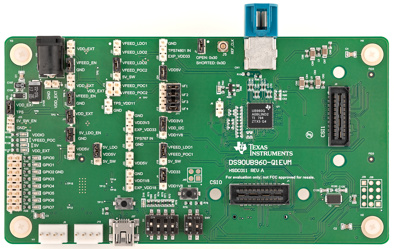
The Texas Instruments DS90UB960-Q1EVM evaluation module (EVM) is a functional board design for evaluating the DS90UB960-Q1, which is a versatile deserializer hub capable of connecting serialized sensor data received from up to 4 independent data streams through an FPD-Link III interface using standard coaxial cables. When coupled with DS90UB953-Q1 serializer, the DS90UB960-Q1 receives data from 2-Megapixel imagers supporting full HD 1080p resolution at 60 Hz frame rates. The DS90UB960-Q1 merges and manages multiple data streams into a MIPI CSI-2 compliant output for interconnect to a downstream processor.
The DS90UB960-Q1EVM is configured for communication with up to four DS90UB953-Q1 serializers. It features a quad mini-FAKRA connector, a Quad Mini-Fakra to 4x Single FAKRA cable assembly, and configurable power-over-coax voltage for connecting up to four camera modules (not included). Each of the FPD-Link III interfaces also includes a separate low latency bi-directional control channel that conveys control information from an I2C port. General purpose I/O signals such as those required for camera synchronization and functional safety features also make use of this bi-directional control channel to program registers in the DS90UB960-Q1 as well as the connected serializers and any remote I2C device attached to the serializers. The EVM also features an on-board MSP430 which functions as a USB2ANY bridge for interfacing with a PC for evaluation. The USB2ANY interfaces with the Analog LunchPAD GUI tool.
The EVM is not intended for EMI testing. The EVM was designed for easy accessibility to device pins with tap points for monitoring or applying signals, additional pads for termination, and multiple connector options.
 Figure 1-1 DS90UB960-Q1EVM