-
How to Isolate Signal and Power in Isolated CAN Systems
How to Isolate Signal and Power in Isolated CAN Systems
1 Application Brief
Introduction:
With the increase in the usage of signal isolation in many industrial and automotive applications, the need for isolated power has also increased. The benefits of isolation are lost if the power supplies on either side of the isolation barrier are simply shorted. At the same time, if the isolated power sub-systems are not designed carefully, it affects the overall system performance like temperature rise due to poor power transfer efficiency, data corruption due to emissions, and so on. To simplify the design process of isolated CAN sub-systems, this document provides various options (discrete and integrated) to isolate CAN signals and power.
Discrete implementation of isolated power:
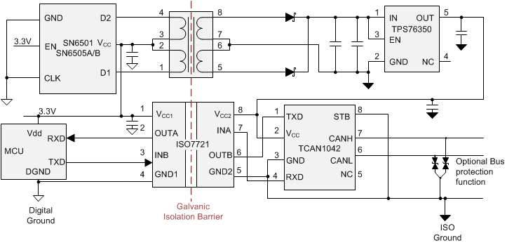
Figure 1 shows an example of a discrete isolated signal and power solution for an isolated CAN subsystem. The isolated CAN functionality is achieved using a digital isolator ISO7721, which provides one channel in each direction for transmit (TXD) and receive (RXD) signals, and TCAN1042H, a fault protected CAN transceiver with flexible data-rate.
The SN6501 device is a push-pull transformer driver that can be used in conjunction with an external transformer, rectifier diodes and an LDO to generate the isolated power supply. Depending on the regulation needed, the LDO can be optional. For transformer driver currents up to 350 mA on the primary side of the transformer, the SN6501 would suffice. If the driver current needs to be larger, the SN6505A or SN6505B with 1A drive current may be more suitable.
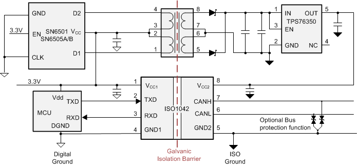
By replacing the discrete isolator and CAN from Figure 1 with an isolated CAN device allows for a simplified signal chain as depicted in Figure 2. The isolated power solution is the same as the previous discrete implementation. The isolated CAN ISO1042 device in this design reduces the device count by one, improves the loop time and provides high levels of protection. This solution has all of the benefits of the previous discrete solution but with no additional drawbacks.
If there are multiple isolated CAN devices in the system powered from the same isolated power supply, this architecture makes the signal chain section compact as output of the LDO can be used to power all the isolated CAN devices. TIDA-01255 is a detailed reference design for the discrete implementation, that is applicable to automotive and industrial CAN systems.
- Advantages of this solution:
- Higher power transfer efficiency (~ 70-80%) due to use of external transformer.
- Emissions can be minimized by lower switching frequencies of the transformer drivers.
- Flexibility of using any CAN transceiver or digital isolator or single chip isolated CAN.
- Isolated power supply has ability to provide current for multiple isolated CAN transceivers.
 Figure 1-1 Discrete Implementation of Isolated CAN
Sub-system
 Figure 1-2 Discrete Implementation of Isolated CAN
Sub-system With Isolated CAN Transceiver
- Drawbacks of this solution:
- Larger board space due to discrete components.
- Transformers are bulky and require more height, which restricts closer stacking of boards.
- Every isolation component needs to be certified individually.
Isolated CAN with integrated isolated power:
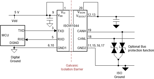
The same functionality of isolated CAN and power can be achieved with ISOW1044: a single device that integrates all the isolation functionality and a CAN FD transceiver into a single 20-SOIC package, as shown in Figure 1-3. The integration of the transformer inside the ISOW1044 chip saves space not only in the X and Y dimension, but also in the Z (height) dimension. Additionally, the ISOW1044 contains a separate 10 Mbps GPIO channel which can help to further remove other digital isolators or optocouplers from the board.
 Figure 1-3 Integrated Implementation of
Isolated CAN Sub-system
Figure 1-3 Integrated Implementation of
Isolated CAN Sub-system- Advantages of this solution:
- Compact solution, including lower height of the solution.
- Ease of certification and design due to only one isolated component.
- Reduces the burden of finding a suitably-rated transformer.
- The low-emissions design ensures the final system is capable of meeting CISPR 32 radiated emissions Class B limit lines with just two ferrite beads on a two-layer PCB.
- Drawbacks of this
solution:
- Power transfer efficiency is limited to 47% due to the on-chip transformers.
- Since the transformer is integrated, the emissions are generally higher than discrete implementation due to higher switching frequencies.
- Best suited for systems where isolated power is primarily needed for a single CAN interface as the device only generates isolated power for the internal CAN transceiver with up to 20-mA extra output current.
Special case
There could be instances when 3.3 V or 5 V is not readily available to power up the primary side in either the discrete or the integrated isolated power implementations. For example, PLC applications may have a 24-V supply while automotive applications may have a 12-V battery. In these cases a suitable LDO can be added before the transformer driver SN650x as shown in Figure 4 to step down the voltage to the 5-V levels needed by the transformer driver. The transformer is driven by the high voltage power supply and the turns ratio is chosen to provide 5 V on the secondary side to power the isolated CAN. Since the transformer center tap is connected to higher voltage than the SN650x ratings, high voltage FETs are used to protect the outputs D1, D2 of the transformer drivers. Care must be taken to size the FETs to keep the RDS(ON) as low as possible to reduce loss of efficiency.
 Figure 1-4 High Primary-Side Voltage
Conclusion
Choosing the right components for designing isolated CAN systems is critical. The selection of the discrete or integrated solutions depends on the trade-offs between size, ease of design versus efficiency, emissions. Discrete implementation of isolated power supplies provides higher efficiency of power transfer, lower emissions while the integrated solution for isolated power provides a compact solution for space critical applications.
| Device | Optimized Parameters | Performance Trade-Off |
|---|---|---|
| ISO1044 | Ultra-small isolated CAN transceiver | 3 kVRMS isolation and ±58-V bus fault protection |
IMPORTANT NOTICE AND DISCLAIMER
| TI PROVIDES TECHNICAL AND RELIABILITY DATA (INCLUDING DATASHEETS), DESIGN RESOURCES (INCLUDING REFERENCE DESIGNS), APPLICATION OR OTHER DESIGN ADVICE, WEB TOOLS, SAFETY INFORMATION, AND OTHER RESOURCES “AS IS” AND WITH ALL FAULTS, AND DISCLAIMS ALL WARRANTIES, EXPRESS AND IMPLIED, INCLUDING WITHOUT LIMITATION ANY IMPLIED WARRANTIES OF MERCHANTABILITY, FITNESS FOR A PARTICULAR PURPOSE OR NON-INFRINGEMENT OF THIRD PARTY INTELLECTUAL PROPERTY RIGHTS. |
| These resources are intended for skilled developers designing with TI products. You are solely responsible for (1) selecting the appropriate TI products for your application, (2) designing, validating and testing your application, and (3) ensuring your application meets applicable standards, and any other safety, security, or other requirements. These resources are subject to change without notice. TI grants you permission to use these resources only for development of an application that uses the TI products described in the resource. Other reproduction and display of these resources is prohibited. No license is granted to any other TI intellectual property right or to any third party intellectual property right. TI disclaims responsibility for, and you will fully indemnify TI and its representatives against, any claims, damages, costs, losses, and liabilities arising out of your use of these resources. |
| TI’s products are provided subject to TI’s Terms of Sale (www.ti.com/legal/termsofsale.html) or other applicable terms available either on ti.com or provided in conjunction with such TI products. TI’s provision of these resources does not expand or otherwise alter TI’s applicable warranties or warranty disclaimers for TI products. |
| Mailing Address: Texas Instruments, Post Office Box 655303, Dallas, Texas 75265
Copyright © 2020, Texas Instruments Incorporated |