SLAA979 November 2020 MSP430FR2422 , MSP430FR2433
Application Brief
One common MSP430 application is to mix colors in an RGB LED using Pulse-width Modulation (PWM) outputs from the Timer module. An RGB LED is an LED with red, green, and blue LEDs in one package sharing a common anode or cathode. RGB LEDs are commonly used in many diverse applications including stage lighting, indoor lighting, outdoor lighting, and home decorations. Each individual LED's current is controlled by using a current-limiting resistor and a PWM waveform with a variable duty cycle. By individually controlling the PWM duty cycle of the red, green, and blue LEDs inside the RGB LED, a wide array of color hues can be observed that range the scale of the visible light spectrum. Typically, RGB colors range in value from 0-255 (decimal). Protocols such as universal asynchronous receiver/transmitter (UART) can communicate to the MCU what color is to be outputted to the RGB LED by sending a 24-bit hex value that contains the values for all colors or individually sending the byte value to each color. In addition, interrupts can be used to update the PWM duty cycles via UART while keeping the MCU in a low-power state.
Implementation
This implementation uses a UART to send 8-bit values (0-255 decimal) to the red, green, and blue LEDs. The firmware takes those values, converts it into a proportional PWM duty cycle waveform, and outputs the signal to their respective RGB pins of the LED. A graphical user interface (GUI) was developed to select RGB color hues individually or simultaneously using a slider, number input, or a color wheel palette.
Timer_A0 and Timer_A1 are configured to output varying duty cycle PWM waveforms on P1.2 (red), P1.4 (green), and P1.5 (blue). P1.2 is tied to TA0.2 by selecting the secondary I/O function for that pin, and TA0.2 corresponds to Timer_A0 and its Compare/Capture Registers 0 and 2. Therefore, the compare/capture registers for Timer_A0 are configured so that the duty cycle is adjustable by adjusting TA0CCR2, with the duty cycle equal to TA0CCR2/TA0CCR0. A similar process is used for configuring P1.4 (TA1.2) and P1.5 (TA1.1) using Timer_A1 and its Compare/Capture Registers 0, 1, and 2.
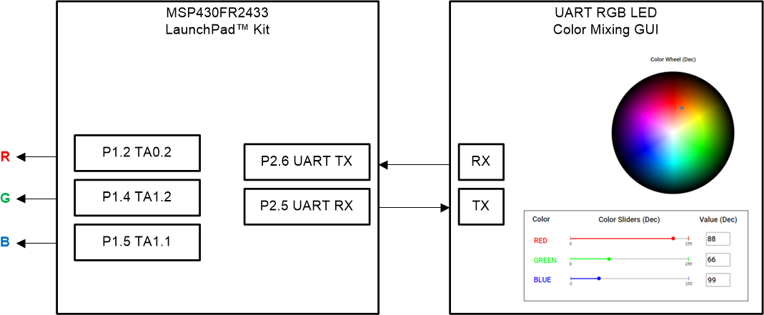
Figure 1-1 shows the block diagram for this implementation.
 Figure 1-1 Implementation Overview
The MSP430FR2433 LaunchPad™ Development Kit is used with this example project, but it can be used for any MSP430 microcontroller with proper code migration. Backchannel UART interface on eZ-FET of the LaunchPad kit is used for UART communication with the GUI, however, the UART pins must connect to P2.5 and P2.6 rather than its intended configuration (P1.5 and P1.4) since those pins are being used respectively for TA1.1 and TA1.2. To do this, remove the RXD and TXD jumpers and use female-to-female jumpers to connect the top pins of RXD and TXD (on the eZ-FET Debug Probe side) to P2.5 and P2.6, respectively. These pins correspond with UCA1 (instance 1 of the eUSCI_A module) rather than UCA0 (used in other Housekeeping examples), so the firmware has been updated to configure the UART properly.
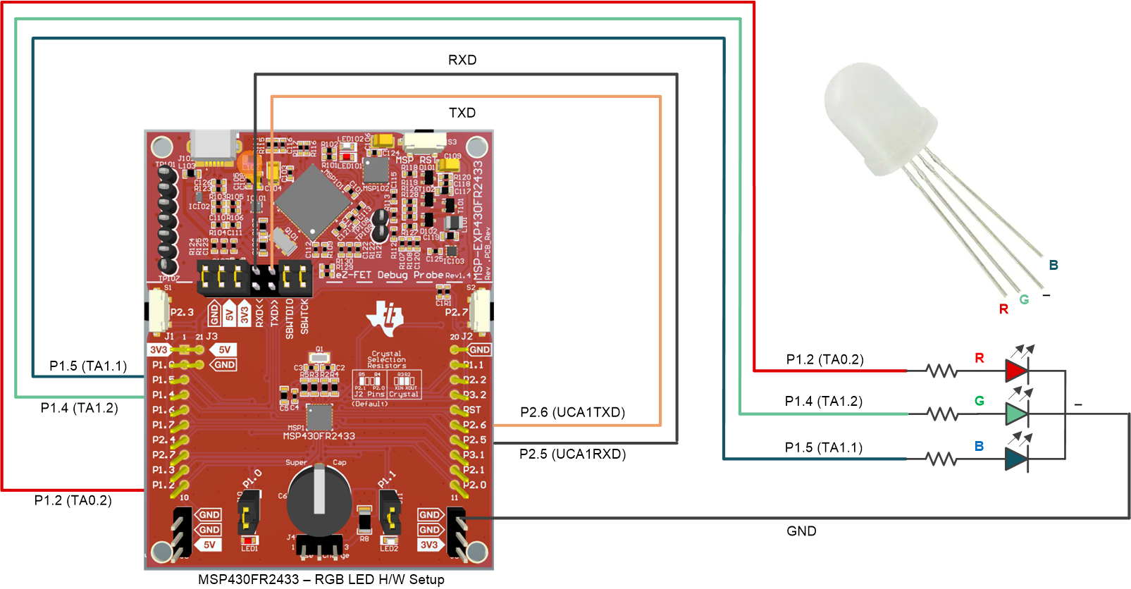
The COM channel number information can be found in the PC device management under the control panel. Figure 1-2 shows the MSP430FR2433 LaunchPad kit including eZ-FET, UART into P2.5 (RXD) and P2.6 (TXD), and RGB PWM outputs on P1.2 (TA0.2), P1.4 (TA1.2), and P1.5 (TA1.1). In this example, a common-cathode RGB LED with current-limiting series resistors was used, as shown on the right hand side. Use female-to-female jumpers to connect the series resistors and RGB as shown in the schematic and connect the common cathode to the GND pin of the Launchpad. It may be helpful to use a breadboard if necessary. Ensure resistor values are selected based on the current ratings and forward voltage drops of the individual LEDs.
 Figure 1-2 MSP430FR2433 LaunchPad and
Connections
Figure 1-2 MSP430FR2433 LaunchPad and
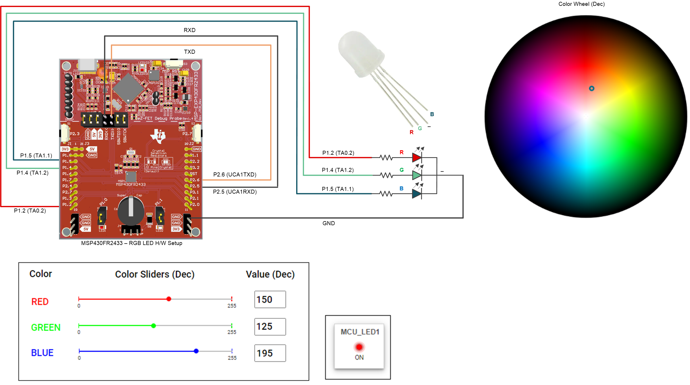
ConnectionsAs shown in Figure 1-3, a GUI is used to set the RGB color values to output to the LED using individual color sliders or input boxes, or simultaneously using a clickable color wheel palette. To use the sliders, simply drag the slider to the desired number from 0-255 (decimal) of the color value. To use the input box, type in the desired number from 0-255 (decimal) of the color value. To use the color wheel, click or drag the marker to the desired color. This will output that color in real-time to the RGB LED.
The eUSCI_A1 peripheral was used in UART mode to enable commands to be received on P2.5/UCA1RXD and transmitted on P2.6/UCA1TXD. The eZ-FET inside of the LaunchPad was used for evaluation. A baud rate of 9600 must be selected with one stop bit and no parity. If the GUI is enabled in software, the PC sends a byte of data to the MCU via UART that contains the individual color value in hexadecimal. If the color wheel is used, the PC will send 3 bytes of data containing the RGB values in hex.
If not using the GUI, then the MCU will output the RGB-mixed color after every 3 bytes of data are transmitted from the PC. For instance, if the PC sends the data 0xFF, 0x00, and 0x00, then the RGB LED will output red because the first byte is the red value, the second byte is the green value, and the third byte is the blue value.
 Figure 1-3 RGB LED Color Mixing GUI.
 Performance
The operation of the demo can be run as described in the implementation section regarding the use of UART to configure the PWM duty cycle of the red, green, and blue LEDs inside of the RGB LED. P1.2 (TA0.2), P1.4 (TA1.2), and P1.5 (TA1.1) are used to output controllable PWM waveforms to the RGB LED in order to create any hue of color desired by the user. Figure 1-3 shows the GUI interface with selectable color sliders, input boxes, and a color wheel as options for the user to determine what intensities of red, green, and blue are to be mixed and outputted. When the color sliders, input boxes or color wheel values are changed, the values will update automatically for the other and the RGB LED will output that color mix immediately.
To Get Started
- Watch the training video “UART RGB Color Mixing with a Housekeeping MCU” to learn how to use the GUI to mix colors on an RGB LED.
- Order a MSP430FR2433 LaunchPad kit to evaluate the UART RGB Color Mixing example code.
- Download and test this example with the UART RGB Color Mixing example GUI to mix any combination of red, green, and blue colors in a RGB LED.
- Evaluate the UART RGB Color Mixing example code for the MSP430FR2433 LaunchPad kit.
Device Recommendations
| Part Number | Key Features |
|---|---|
| MSP430FR2433 | 16KB FRAM, 4KB SRAM, 10-bit ADC, UART/SPI/I2C, Timer |
| MSP430FR2422 | 8KB FRAM, 2KB SRAM, 10-bit ADC, UART/SPI/I2C, Timer |