SBOA167B December 2016 – September 2021 INA199 , INA199-Q1 , INA210 , INA210-Q1 , INA211 , INA211-Q1 , INA212 , INA212-Q1 , INA213 , INA213-Q1 , INA214 , INA214-Q1 , INA215 , INA215-Q1 , INA219 , INA220 , INA220-Q1 , INA226 , INA226-Q1 , INA228 , INA228-Q1 , INA229 , INA229-Q1 , INA230 , INA231 , INA233 , INA234 , INA237 , INA237-Q1 , INA238 , INA238-Q1 , INA239 , INA239-Q1 , INA260 , INA301 , INA301-Q1 , INA302 , INA302-Q1 , INA303 , INA303-Q1
1
Current measurements are used in electronic systems to provide feedback verifying operation is within acceptable margins and to detect potential fault conditions. Analyzing a system’s current level can diagnose unintended or unexpected operating modes allowing for adjustments to be made to improve reliability or to protect the system components from damage.
Current is a signal that is difficult to measure directly. However, there are several measurement methods that are capable of measuring the effect of flowing current. Current passing through a wire produces a magnetic field that can be detected by magnetic sensors (hall-effect and fluxgate for example). Current measurements can also be made by measuring the voltage developed across a resistor as current passes through. This type of resistor is called a current sensing, or shunt, resistor.
For current ranges reaching up to 100 amps on voltage rails below 100 volts, measuring current with shunt resistors are typically preferred. The shunt resistor approach commonly provides a physically smaller, more accurate and temperature stable measurement compared to a magnetic solution.
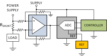
For the system’s current information to be evaluated and analyzed, it must be digitized and sent to the system controller. There are many methods for measuring and converting the signal developed across the shunt resistor. The most common approach involves using an analog front-end to convert the current sensing resistor’s differential signal to a single-ended signal. This single-ended signal is then connected to an analog to digital converter (ADC) that is connected to a microcontroller. Figure 1-1 illustrates the current sensing signal chain.
 Figure 1-1 Current Sensing Signal
Path
Figure 1-1 Current Sensing Signal
PathTo optimize the current sensing signal chain, the shunt resistor value and amplifier gain must be appropriately selected for the current range and full-scale input range of the ADC. The selection of the shunt resistor is based on a compromise between measurement accuracy and power dissipation across the shunt resistor. A large value resistor will develop a larger differential voltage as the current passes through. The measurement errors will be smaller due to the fixed amplifier offset voltage. However, the larger signal creates a larger power dissipation across the shunt resistor (P = I2R). A smaller shunt resistor develops a smaller drop across the shunt resistor reducing the power dissipation requirements but also increases the measurement errors as the amplifier’s fixed offset errors become a larger percentage of the signal.
The amplifier gain is selected to ensure that the amplifier’s output signal will not exceed the ADCs full-scale input range at the full-scale input current level.
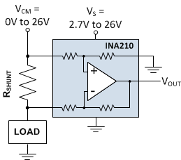
The INA210 is a dedicated current sense amplifier that integrates the external gain setting resistors as shown in Figure 1-2. Bringing these gain resistors internal to the device allows for increased matching and temperature drift stability compared to typical external gain setting resistors. Space saving QFN packages significantly reduce the board space requirements of an operational amplifier and external gain resistors. Current sense amplifiers are commonly available in multiple fixed gain levels to better optimize the pairing with shunt resistor values based on the input current and ADC full-scale input ranges.
 Figure 1-2 INA210: Current Sensing
Amplifier
Figure 1-2 INA210: Current Sensing
AmplifierFigure 1-1 shows the operational amplifier measuring the differential voltage developed across the shunt resistor and sending the amplified signal to the single ended ADC. A fully differential input ADC can monitor the differential voltage directly across the shunt resistor. One drawback to using a typical ADC is reduced input range used. The signal developed across a shunt resistor will be small to limit the power dissipation requirements of this component. Lower ADC resolutions will also impact the small signal measurement accuracy.
The ADC reference will also be an additional error source that must be evaluated in this signal path. A typical ADC will feature an input range that is based on the converter's reference voltage. The actual reference voltage range varies from device to device but is typically in the 2 V to 5 V range. The LSB (least significant bit) is based on the full-scale range and resolution of the converter. For example, a 16-bit converter with a full-scale input range of 2.5 V, the LSB value is roughly 38 µV.
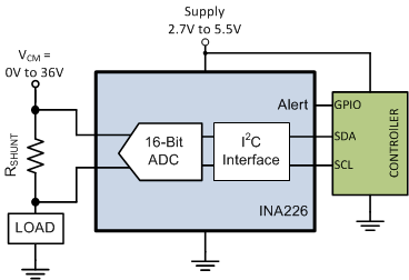
The INA226 is a specialized ADC designed specifically for bi-directional current sensing applications. Unlike typical ADCs, this 16-bit converter features a full-scale input range of +/- 80 mV eliminating the need to amplify the input signal to maximize the ADC's full-scale input range. The INA226 is able to accurately measure small shunt voltages based on the device's maximum input offset voltage of 10 µV and an LSB size of 2.5 µV. The INA226 provides 15 times more resolution than the equivalent standard 16-bit ADC with a full-scale input range of 2.5 V. The specialization of the INA226 makes this device ideal for directly monitoring the voltage drop across the current sensing resistor as shown in Figure 1-3.
 Figure 1-3 Digital Current/Power
Monitor
Figure 1-3 Digital Current/Power
MonitorIn addition to the ability to directly measure voltage developed across the shunt resistor as current passes through, the INA226 can also measure the common-mode voltage. The INA226 has an input multiplexer allowing the ADC input circuitry to switch between the differential shunt voltage measurement and the single-ended bus voltage measurement.
The current sensing resistor value present in the system can be programmed into a configuration register on the INA226. Based on this current sensing resistor value and the measured shunt voltage, on-chip calculations convert of the shunt voltage back to current and can provide a direct readout of the corresponding power level of the system. Performing these calculations on-chip reduces processor resources that would normally be required to convert this information.
Alternate Device Recommendations
For applications with lower performance requirements, using the INA199 still takes advantage of the benefits of the dedicated current sense amplifier. For applications implementing over-current detection, the INA301 features an integrated comparator to allow for on-chip over-current detection as fast as 1µs. For applications with lower performance requirements, using the INA219 is able to take advantage of the specialized current sensing ADC.
| Device | Optimized Parameter | Performance Trade-Off |
|---|---|---|
| INA199 | Lower Cost | Higher VOS and Gain Error |
| INA301 | Signal Bandwidth, On-Board Comparator | Larger Package: MSOP-8 |
| INA219 | Smaller Package Digital Monitor, Lower Cost | Higher VOS and Gain Error |
| INA190 | More Accurate | N/A |
| SBOA162 | Measuring Current To Detect Out-of-Range Conditions |
| SBOA165 | Precision Current Measurement On High Voltage Power Rail |
| SBOA160 | High Precision, Low-Drift In-Line Motor Current Measurements |
| SBOA161 | Low-Drift, Low-Side Current Measurements for Three-Phase Systems |