• Menu
  • Product
  • Email
  • PDF
  • Order now
  • CC256x versus HCI Commands

    • SWRA751 September   2022


  • CONTENTS
  • SEARCH
  • CC256x versus HCI Commands
  1.   Introduction
  2.   Trademarks
  3. 1Command Packet
  4. 2Event Packet
  5. 3HCI Commands
    1. 3.1 HCI Commands List Format
    2. 3.2 Support HCI Commands Detailed Description
      1. 3.2.1  HCI_VS_Write_BD_Addr (0xFC06)
      2. 3.2.2  HCI_VS_Write_CODEC_Config (0xFD06)
      3. 3.2.3  HCI_VS_Write_CODEC_Config_Enhanced (0xFD07)
      4. 3.2.4  HCI_VS_DRP_Read_BER_Meter_Result (0xFD13)
      5. 3.2.5  HCI_VS_DRPb_Tester_Con_RX (0xFD17)
      6. 3.2.6  HCI_VS_LE_Enable (0xFD5B)
      7. 3.2.7  HCI_VS_Set_LE_Test_Mode_Parameters (0xFD77)
      8. 3.2.8  HCI_VS_DRPb_Enable_RF_Calibration (0xFD80)
      9. 3.2.9  HCI_VS_DRPb_Tester_Con_TX (0xFD84)
      10. 3.2.10 HCI_VS_DRPb_Tester_Packet_TX_RX (0xFD85)
      11. 3.2.11 HCI_VS_DRPb_Reset (0xFD88)
      12. 3.2.12 HCI_VS_DRPb_BER_Meter_Start (0xFD8B)
      13. 3.2.13 HCI VS LE Read Ber Test Results (0xFDAE)
      14. 3.2.14 HCI_VS_Read_RSSI (0xFDFC)
      15. 3.2.15 HCI_VS_Write_SCO_Configuration (0xFE10)
      16. 3.2.16 HCI_VS_Set_Pcm_Loopback_Enable (0xFE28)
      17. 3.2.17 HCI_VS_Read_Hardware_Register (0xFF00)
      18. 3.2.18 HCI_VS_Write_Hardware_Register (0xFF01)
      19. 3.2.19 HCI_VS_Update_UART_HCI_Baudrate (0xFF36)
      20. 3.2.20 HCI_VS_Set_Supported_Features (0xFF26)
      21. 3.2.21 HCI_VS_HCILL_Parameters (0xFD2B)
      22. 3.2.22 HCI_VS_Sleep_Mode_Configurations (0xFD0C)
      23. 3.2.23 HCI_VS_Get_System_Status (0xFE1F)
      24. 3.2.24 HCI_VS_Read_Patch_Version (0xFF22)
      25. 3.2.25 HCI_VS_DRPb_Set_Power_Vector (0xFD82)
      26. 3.2.26 HCI_VS_DRPb_Set_Class2_Single_Power (0xFD87)
      27. 3.2.27 HCI_VS_LE_Output_Power (0xFDDD)
      28. 3.2.28 HCI_VS_A3DP_Codec_Configuration (0xFD8E)
      29. 3.2.29 HCI_VS_AVPR_Enable (0xFD92)
      30. 3.2.30 HCI_VS_A3DP_Open_Stream (0xFD8C)
      31. 3.2.31 HCI_VS_A3DP_Close_Stream (0xFD8D)
      32. 3.2.32 HCI_VS_A3DP_Start_Stream (0xFD8F)
      33. 3.2.33 HCI_VS_A3DP_Stop_Stream (0xFD90)
      34. 3.2.34 HCI_VS_A3DP_Sink_Codec_Configuration (0xFD9C)
      35. 3.2.35 HCI_VS_A3DP_Sink_Open_Stream (0xFD9A)
      36. 3.2.36 HCI_VS_A3DP_Sink_Close_Stream (0xFD9B)
      37. 3.2.37 HCI_VS_A3DP_Sink_Start_Stream (0xFD9D)
      38. 3.2.38 HCI_VS_A3DP_Sink_Stop_Stream (0xFD9E)
      39. 3.2.39 HCI_VS_WBS_Associate (0xFD78)
      40. 3.2.40 HCI_VS_WBS_Disassociate (0xFD79)
  6. 4General Hardware Errors
  7. 5Revision History
  8. IMPORTANT NOTICE
search No matches found.
  • Full reading width
    • Full reading width
    • Comfortable reading width
    • Expanded reading width
  • Card for each section
  • Card with all content


APPLICATION NOTE

CC256x versus HCI Commands

1 Introduction

Bluetooth® systems consists of a host and a controller. The BT SIG has created a standard protocol for the host to communicate with the controller. This is called the Host Controller Interface (HCI) which is specified in the BT Core 4.1 specification Volume 2 Part E. The HCI provides a uniform command interface to a Controller. There are some commands which are not listed in the specifications and they are specific to the device itself. These commands are vendor-specific commands (VS) generally used for testing and debugging purposes. For further details on testing command sequences, refer to CC256x Testing Guide.

Figure 1-1 HCI Commands VS
GUID-20220726-SS0I-PBQF-DXSF-RK9WZWKQ8L97-low.jpg

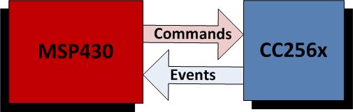
As shown in the diagram above, the host (MSP430) sends HCI commands to the controller (CC256x). The controller then sends HCI events to the host as a response to the HCI commands. All HCI commands follows this format for all packets:

Table 1-1 HCI Packet Format
First Byte Next Bytes
HCI Packet Type HCI packet (variable length)

All HCI commands starts with a byte describing type of packet while the remaining bytes is dependent on the type of HCI packet.

Here is a list of important HCI packet types:

Table 1-2 HCI Packet Types
HCI Packet Type Packet Type Indicator Direction
HCI command packet 0x01 Host to baseband controller
HCI event packet 0x04 Baseband controller to host

Trademarks

Bluetooth® is a registered trademark of Bluetooth SIG.

All trademarks are the property of their respective owners.

1 Command Packet

Most of the HCI packets consist of command packets. The host sends these command packets according to the structure detailed in the tables below and the controller sends responses through event packets back to the host. Command packets are used to configure many aspects of the Bluetooth system ranging from the link layer to the baseband layer.

You can also refer to the Core 4.1 Specification Volume 2, Part E, for the format of these HCI packets.

After the first byte,the remaining bytes depends on what type of packet it is. Of these two packet types, the structure of the HCI command packet is:

Table 1-1 Command Packet

First

Last

16 bit Opcode 8 bit Length Parameters(0,1,3,...,N)
Note: Some commands do not have parameters, thus ends with 0x00 as the length.

Here is a description of the above HCI command packet structure:

Table 1-2 HCI Command Description
Fields Descriptions
Opcode 16 bit unique Opcode for HCI command
Length Length of parameters in bytes
Parameters Specific parameters associated with each command

Taking the command HCI_Read_BD_ADDR, this is an example of a command packet consisting of outgoing data to the controller:

Table 1-3 Command Packet Example
Packet Type Opcode Opcode Length
0x01 0x09 0x10 0x00

In this case, the length is zero so no parameters follows afterwards.


Texas Instruments

© Copyright 1995-2025 Texas Instruments Incorporated. All rights reserved.
Submit documentation feedback | IMPORTANT NOTICE | Trademarks | Privacy policy | Cookie policy | Terms of use | Terms of sale