WL18xx Bluetopia PM Bluetooth RF Testing
1 Introduction
This application note is a testing guide for WL18xx Bluetopia devices. PLT tests are used at the production line after designing the board with the Wilink™8 device. This is to sanity check the board works properly and detects any major design issues and manufacturing defects.
Basic RF commands like continuous TX/RX are required as well as part of the Regulatory certification process.
The Connection-less RF tests modes are connection-less RF spectrum tests which uses a spectrum analyzer for verification.
The BT SIG RF Testmode is meant for connecting with a Bluetooth® tester where the Wilink8 device is controlled over the LMP (Link Management Protocol)
There are two ways of issuing these test commands to Wilink8 device
- From a PC that runs HCITester. The commands in sections 2 to 4 are run in HCITester
- On the target using either the BluetopiaPM tool SS1Tool or the Bluez tool hcitool . These commands are used the same way and section 5 shows how to run the tests. Users must run "./SS1BTPM &" before running "./SS1Tool cmd"
Useful Links:
Trademarks
Wilink™ is a trademark of Texas Instruments.
Bluetooth® is a registered trademark of Bluetooth SIG.
All trademarks are the property of their respective owners.
5.1.1 Connectionless RF Tests
The Connection-less RF tests are connection-less RF spectrum tests which uses a spectrum analyzer for verification.
5.1.1.1 Continuous TX
This is a non-packet continuous transmission with either GFSK (BR), π/4-DQPSK (2-EDR) or 8DPSK (3-EDR).
Steps and the HCI commands to put the device in the constant TX mode are:
- run init script.
- #set TxMode: 0x0 = un-modulated Single carrier, 0x1 = GFSK, 0x2 = EDR2, 0x3 = EDR3, 0x4 = BLE, 0x5 = ANT TxMode = 1
- Send_HCI_VS_DRPb_Enable_RF_Calibration_Enhanced 0xFDFB, 0x1, 0xFF, 0x00000000,
0x01
Wait_HCI_Command_Complete_VS_DRPb_Enable_RF_Calibration_Enhanced_Event 5000, any,HCI_VS_DRPb_Enable_RF_Calibration_Enhanced, 0x00 - Send_HCI_VS_DRPb_Tester_Con_TX 0xFDCA, 2402, TxMode, 0, 7, 0x00000000, 0x00000000 //
For TxMode relevant value please see step2
Wait_HCI_Command_Complete_VS_DRPb_Tester_Con_TX_Event 5000, any, HCI_VS_DRPb_Tester_Con_TX, 0x00
The parameters for the HCI_VS_DRPb_Tester_Con_TX are:
- Opcode
- 0xFDCA
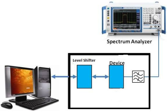
 Figure 5-3 Typical Test Setup for
Continuous TX Mode
 - Frequency
- f=2402 ~ 2479
- Modulation scheme
- 0=CW
- 1=GFSK (BR)
- 2=π/4-DQPSK (2-EDR)
- 3=8DPSK (3-EDR)
- 4=BLE
- 5=ANT
- Test pattern
- 0=PN9
- 1=PN15
- 2=Z0Z0
- 3=all 1
- 4=all 0
- 5=F0F0
- 6=FF00
- Power level index
- 0-7 where 0 is the lowest and 7 is the highest
- Internal setting
- 0x00000000
- Internal setting
- 0x00000000
The HCI commands for Stopping continuous Tx mode are:
TX Stop :
Send_HCI_VS_Write_Hardware_Register 0xFF01, 0x20014044, 0x0010
Wait_HCI_Command_Complete_VS_Write_Hardware_Register_Event 5000, any, HCI_VS_Write_Hardware_Register, 0x00

Send_HCI_VS_Write_Hardware_Register 0xFF01, 0x20014048, 0x0014
Wait_HCI_Command_Complete_VS_Write_Hardware_Register_Event 5000, any, HCI_VS_Write_Hardware_Register, 0x00
Stop PN Generator:
Send_HCI_VS_Write_Hardware_Register 0xFF01, 0x2001900C, 0x0000
Wait_HCI_Command_Complete_VS_Write_Hardware_Register_Event 5000, any, HCI_VS_Write_Hardware_Register, 0x00