-
Ultra-Low Power Sensing Applications With CC13x2/CC26x2 SWRA578B October 2017 – April 2020 CC1312PSIP , CC1312R , CC1314R10 , CC1352P , CC1352P7 , CC1352R , CC2620 , CC2630 , CC2640 , CC2640R2F-Q1 , CC2642R , CC2642R-Q1 , CC2650MODA , CC2652P , CC2652R , CC2652R7 , CC2652RB , CC2652RSIP
-
Ultra-Low Power Sensing Applications With CC13x2/CC26x2
Ultra-Low Power Sensing Applications With CC13x2/CC26x2
Ultra-Low Power Sensing Applications With CC13x2/CC26x2
This application report shows the low-power capabilities of the Sensor Controller Engine in the CC13x2 and CC26x2 devices. The current consumption of different sensors on the BOOSTXL-ULPSENSE is shown, as well as the current consumption of the different sensors of the LPSTK-CC1352R. Comparisons between similar tasks on the Sensor Controller and the System CPU are also shown.
Trademarks
All other trademarks are the property of their respective owners.
1 Overview
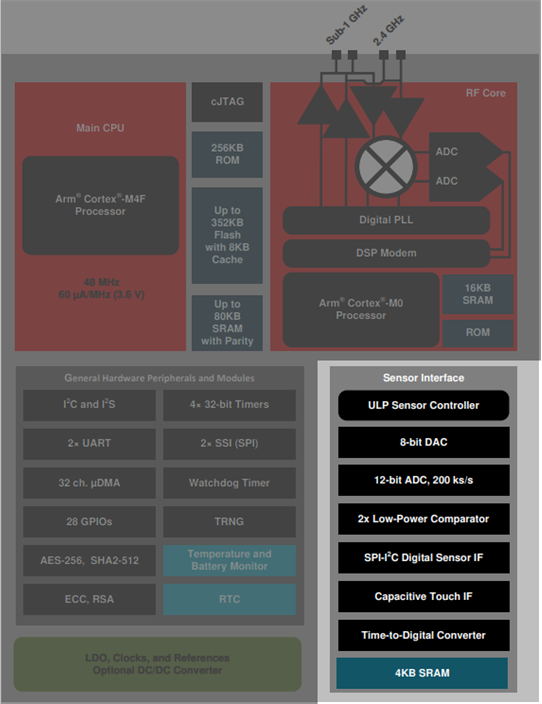
The CC13x2/CC26x2 devices comes equipped with a separate proprietary power-optimized CPU called the Sensor Controller. This CPU can read and monitor sensors or perform other tasks autonomously; thereby significantly reducing power consumption and offloading the system CPU.
 Figure 1. CC13x2/CC26x2 System Block Diagram
The CC13x2/CC26x2 Sensor Controller peripherals include:
- 12-bit ADC capable of sampling analog capable I/Os or internal chip voltages.
- Two comparators, one high performance continuous time comparator and one low-power clocked comparator updated at 32 kHz.
- 8-bit reference DAC capable of supporting the comparators with reference voltages.
- SPI master interface.
- Bit-banged interfaces including I2C master, LCD controller and more.
- Time to digital converter capable of measuring the time between configurable start and stop triggers
- Programmable current source capable of giving out currents between 0 and 20 µA.
- Two simple 16-bit timers.
- 16-bit asynchronous multipurpose timer with 4 capture/compare channels.
- 16-bit pulse counter capable of count rising edges on any digital input pins or comparator output.
- Access to all GPIO pins.
The Sensor Controller can be programmed from the software Sensor Controller Studio. This tool generates a Sensor Controller Interface driver, which is a set of C source files to be compiled into the System CPU application. These source files contain the Sensor Controller firmware image and associated definitions, and generic functions that allow the System CPU application to control the Sensor Controller and exchange data. Full documentation on how to use the Sensor Controller is documented in the Sensor Controller Studio itself.
The programming model and firmware framework are optimized for low overhead when communicating with the System CPU application, low AUX RAM memory footprint, and efficient use of the Sensor Controller's instruction set. To minimize power consumption, the Sensor Controller enters standby mode automatically when it is idle.
2 Measurement Conditions
The measurements were done on projects generated from Sensor Controller Studio without any modifications. The devices were measured without any external disturbance, which is no flow for the flow meter or no movement on the accelerometer, unless specified. Current measurements were done on an Agilent N6705B DC Power Analyzer. The measurements were done in a room temperature environment, with a supply voltage of 3.3 V.
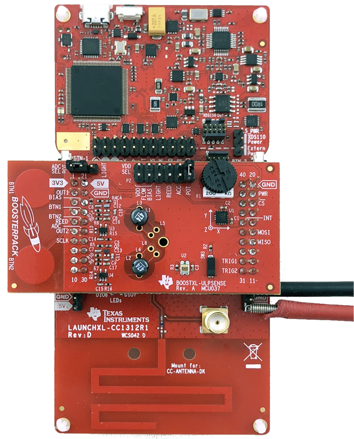
 Figure 2. Measuring on a LAUNCHXL-CC1312R1 with a BOOSTXL-UPLSENSE
 For the current measurement on the LAUNCHXL-CC1312R1 and BOOSTXL-ULPSENSE, all jumpers on the Launchpad are removed, and only the jumpers needed for the test is kept on the BOOSTXL-ULPSENSE. For example for the Potmeter measurement, only the jumper powering the potmeter and the ADC Sel jumper is kept on. The leads of the Agilent N6705B is connected to the 3V3 and GND pins, as shown in the picture above.
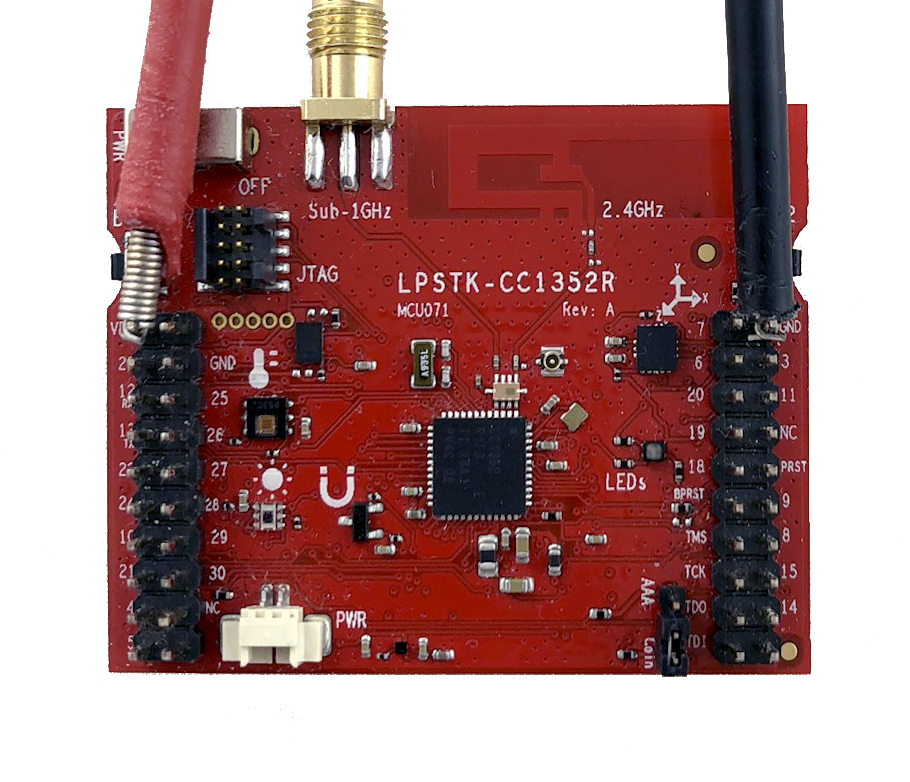
On the LPSTK-CC1352R, the battery is disconnected and JTAG ribbon cable removed. The Agilent N6705B is connected to the VDD and GND pin, as shown in the picture below. The current averages were measured using the Keysight 14585A Control and Analysis Software.
You can read more about power measurements in Measuring CC13xx and CC26xx Current Consumption.
For the measurements on the LAUNCHXL-CC1312R1, each reported current value is the average of 10 measurements on four boards, for a total of 40 measurements. On the LPSTK-CC1352R, each reported current value is the average of 10 measurements on two boards, for a total of 20 measurements.
 Figure 3. Measuring on a LPSTK-CC1352R
 The application report uses the following software and hardware to find the current consumption of the Sensor Controller.