-
Reaping the Benefits of an MSP430™ MCU with Smart Analog Combo in Pulse Oximeter Designs
Reaping the Benefits of an MSP430™ MCU with Smart Analog Combo in Pulse Oximeter Designs
Winter Yu
By measuring changes in infrared and red light absorption in oxygenated or deoxygenated blood, a pulse oximeter clipped to a finger noninvasively monitors a person’s heart rate and blood oxygen saturation (SpO2). Normally, the oxygen saturation of a healthy person’s blood is in the 95% to 100% range. Measuring oxygen saturation using a pulse oximeter like the one shown in Figure 1 can help patients:
- See how well medicines are working
- Determine their ability to handle increased activity levels.
- Determine whether a ventilator is necessary or is working.
- Monitor episodes of sleep apnea.
People who have had health conditions that affect blood oxygen levels such as heart failure or asthma may also use a pulse oximeter.
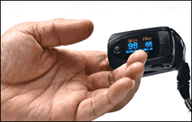 Figure 1 Finger-clamp Pulse Oximeter
Usually, a photodiode measures the infrared and red light passing through the finger. The signal coming out of the photodiode sensor consists of a large DC component and a small AC component (AC is around 0.4% to 10% of DC), shown in Figure 2. The large DC component is a result of absorption by the lesser oxygen-bearing parts of body tissue and scattered light. The small AC component comprises light modulated by the oxygen-bearing parts, such as arteries, as well as noise from ambient light at 50/60 Hz. Both AC and DC components are necessary for SpO2 calculation. To meet the accuracy requirement, a signal conditioning circuit need to be designed to amplify the AC component with resolution increased, DC component and ambient light canceled. However, the signal level varies according to the health conditions of patients, and the position and thickness of the finger. The gain of amplifier need to be dynamically adjusted based on the range of signal to avoid signal saturation.
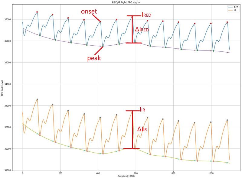 Figure 2 Photoplethysmography Signal
with Large DC and Small AC Component
Figure 2 Photoplethysmography Signal
with Large DC and Small AC ComponentTI has a single-chip pulse oximeter solution based on the MSP430FR2355 microcontroller (MCU) and its built-in smart analog combos (SACs). As a featured peripheral of the MSP430FR2355, the SACs are configurable with software and enable you to perform analog signal conditioning for either the input or output path. Figure 3 illustrates SAC mode.
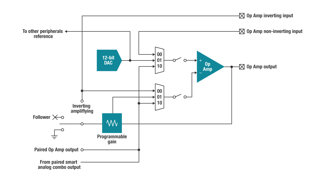 Figure 3 System Block Diagram Using SAC
Mode
Figure 3 System Block Diagram Using SAC
ModeActing as the host MCU in the system, the MSP430FR2355 can provide a true single-chip solution that effectively removes the need for an external amplifier and digital-to-analog converter (DAC), reducing system complexity and cost. Plus, you can configure each SAC module as an operational amplifier, programmable gain amplifier or 12-bit DAC. Figure 4 is a system block diagram of a pulse oximeter using an MSP430FR2355 MCU.
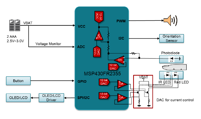 Figure 4 A Sample Pulse Oximeter System Block Diagram
The sample pulse oximeter solution in Figure 4 illustrates four SAC modules:
- Two SAC modules as a DAC with 12-bit resolution, for driving infrared and red LEDs with adjustable and stable current.
- One SAC module as a transimpedance amplifier, with 50 pA of input bias current for measuring photodiode current.
- One SAC module as a PGA, with 32 times gain working with the DAC used as DC compensation and an AC amplifier.
Besides built-in smart analog combos, the low to 42nA standby current, small package, memory configuration and communication interface is very suitable for a low-cost pulse oximeter design.
Figure 5 lists the detailed MSP430FR2355 MCU’s on-chip analog and digital features.
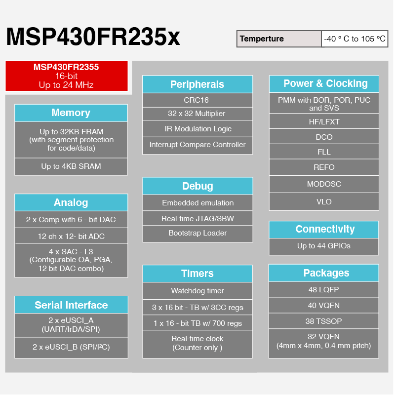 Figure 5 MSP430FR2355 On-chip
Features
Figure 5 MSP430FR2355 On-chip
FeaturesConclusion
The MSP430FR2355 is an ultra-low-power and low-cost 16-bit reduced instruction set computer MCU with many analog signal-chain peripherals. The four smart analog combs effectively remove the need for an external amplifier and digital-to-analog converter (DAC), reducing system complexity and cost. The low power and VQFN32 (4-mm-by-4-mm 32-pin) package is a good fit for a portable device such as a pulse oximeter. The MSP430 MCU along with the online software (https://www.ti.com/tool/MSPWARE) and hardware resources can help you design a pulse oximeter quickly.
Additional Resources
- Read the application reports, “MSP430’s Analog Combo Enables True Single-Chip Pulse Oximeter Designs” and “How to Use the Smart Analog Combo in MSP430 MCUs.”
- Read the technical article, “How to design an infrared thermometer quickly.”
IMPORTANT NOTICE AND DISCLAIMER
TI PROVIDES TECHNICAL AND RELIABILITY DATA (INCLUDING DATASHEETS), DESIGN RESOURCES (INCLUDING REFERENCE DESIGNS), APPLICATION OR OTHER DESIGN ADVICE, WEB TOOLS, SAFETY INFORMATION, AND OTHER RESOURCES “AS IS” AND WITH ALL FAULTS, AND DISCLAIMS ALL WARRANTIES, EXPRESS AND IMPLIED, INCLUDING WITHOUT LIMITATION ANY IMPLIED WARRANTIES OF MERCHANTABILITY, FITNESS FOR A PARTICULAR PURPOSE OR NON-INFRINGEMENT OF THIRD PARTY INTELLECTUAL PROPERTY RIGHTS.
These resources are intended for skilled developers designing with TI products. You are solely responsible for (1) selecting the appropriate TI products for your application, (2) designing, validating and testing your application, and (3) ensuring your application meets applicable standards, and any other safety, security, or other requirements. These resources are subject to change without notice. TI grants you permission to use these resources only for development of an application that uses the TI products described in the resource. Other reproduction and display of these resources is prohibited. No license is granted to any other TI intellectual property right or to any third party intellectual property right. TI disclaims responsibility for, and you will fully indemnify TI and its representatives against, any claims, damages, costs, losses, and liabilities arising out of your use of these resources.
TI’s products are provided subject to TI’s Terms of Sale (www.ti.com/legal/termsofsale.html) or other applicable terms available either on ti.com or provided in conjunction with such TI products. TI’s provision of these resources does not expand or otherwise alter TI’s applicable warranties or warranty disclaimers for TI products.
Mailing Address: Texas Instruments, Post Office Box 655303, Dallas, Texas 75265
Copyright © 2023, Texas Instruments Incorporated