-
How to Use the Smart Analog Combo in MSP430™ MCUs SLAA833A May 2018 – October 2019 MSP430FR2353 , MSP430FR2355
-
How to Use the Smart Analog Combo in MSP430™ MCUs
- How to Use the Smart Analog Combo in MSP430™ MCUs
- Revision History
- IMPORTANT NOTICE
How to Use the Smart Analog Combo in MSP430™ MCUs
How to Use the Smart Analog Combo in MSP430™ MCUs
Operational amplifiers (op amps or OAs) are used extensively in sensing and measurement applications. MSP430™ microcontrollers (MCUs) provide full signal chain implementation with the integrated smart analog combo (SAC) to replace external op amps. The smart analog combo is a configurable analog peripheral that includes a high-performance low-power op amp, a programmable gain amplifier (PGA) with gain up to 33, and a 12-bit digital-to-analog converter (DAC). This application report describes how to use the SAC module in MSP430 MCUs. SAC concept, operation modes, internal connection, ROM-based driver library, and design consideration are described. This application report also describes SAC use cases and the benefits of using the module in smoke detector and current loop applications.
Trademarks
MSP430 is a registered trademark of Texas Instruments.
All other trademarks are the property of their respective owners.
1 Introduction
Various sensors convert physical quantities in the real world into electrical signals. The sensor's output signal is usually with small amplitude and noise, so that it must be amplified and filtered. The operational amplifier is a vital component for signal conditioning like amplification and filtering. After signal conditioning, an analog-to-digital converter (ADC) is used to convert the analog signal into a digital signal for the processor or controller to analyze. MSP430 MCUs provide signal chain elements with highly integrated analog peripherals for sensing and measurement applications. Within the MSP430FR23xx family of MCUs, the integrated smart analog combo is a key differentiated analog peripheral that includes a high-performance low-power operational amplifier, a PGA with gain up to 33, and a 12-bit digital-to-analog converter. The smart analog combo provides flexible analog configuration on one chip that saves BOM cost and PCB size. This application report describes how to use the smart analog combo in MSP430 MCUs. It introduces the theory of operation, operation modes, internal connection, ROM-based driver library, design considerations, and application use cases.
1.1 Smart Analog Combo (SAC) Concept
The SAC module includes one programmable gain amplifier (PGA) and one 12-bit digital-to-analog converter (DAC). The module can be used for signal conditioning in input path and waveform generation in output path. There are three different configuration levels for the SAC module: SAC-L1, SAC-L2, and SAC-L3.
- SAC-L1 is the minimum feature set and integrates only the operational amplifier.
- SAC-L2 includes the operational amplifier and a feedback resistance ladder to form a PGA with gain up to 33.
- SAC-L3 is the maximum feature set that integrates the SAC-L2 PGA and a 12-bit DAC.
Different MSP430 MCUs have different SAC configuration levels. For example, the MSP430FR2311 integrates one SAC-L1 module, and the MSP430FR2355 integrates four SAC-L3 modules. For the SAC configuration level and quantity on a specific MCU, see the device-specific data sheet.
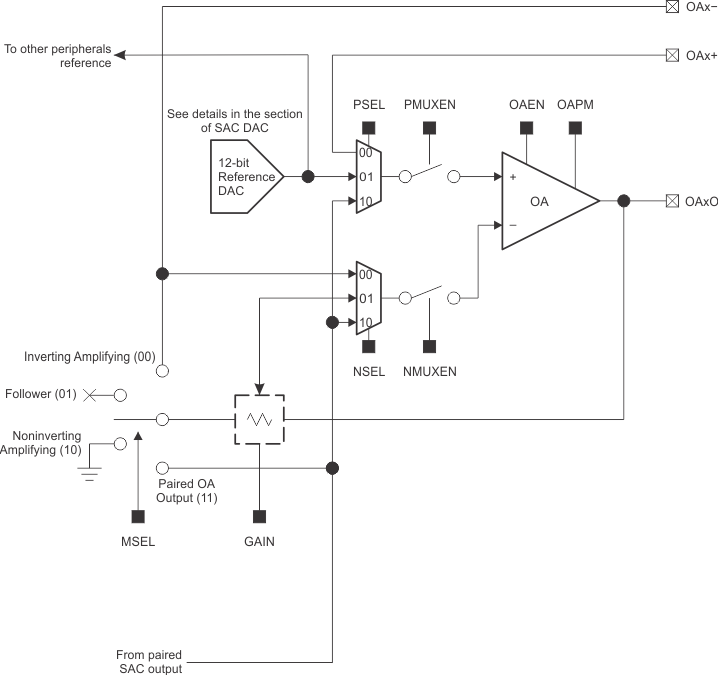
Figure 1 shows the block diagram of SAC-L3 module. The integrated amplifier supports rail-to-rail input and rail-to-rail output. The two internal multiplexers support multiple input selections for the operational amplifier (OA). The op-amp power mode (OAPM) control bit selects the OA power mode. In high-power mode, the OA provides higher gain bandwidth and slew rate. If lower power consumption is more critical in the application, select the OA low-power mode by setting the OAPM bit to 1. The feedback resistance ladder connects the OA output with the negative input as the feedback routing. With the feedback routing, the OA supports both inverting PGA mode and noninverting PGA mode. A 12-bit DAC is also integrated in the SAC-L3 module. The DAC can be used to generate a bias voltage to the OA or can work with OA to drive a waveform output on the pad.
 Figure 1. Smart Analog Combo Block Diagram
 1.2 Single-Supply Amplifier Design Consideration
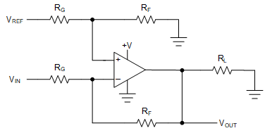
Because the Smart Analog Combo (SAC) is one of the analog peripherals in the MSP430 MCU, the SAC is supplied by the power pin on the MSP430 MCU. The integrated OA is a single-supply design with a wide supply voltage range from 2 V to 3.6 V. The OA inputs are referenced to ground. A dual-supply OA circuit design is straightforward, because the OA inputs and output are referenced to the normally grounded center of the supplies. The single-supply OA design is a little more complicated than a dual-supply OA as some form of biasing is usually required for single-supply OA. The OA input and output voltages must be within its two power rails. The SAC does not support negative voltage input or output. When the SAC is in inverting amplifier mode, biasing on the positive input is essential to avoid clipping distortion. Figure 2 shows the typical circuit for single-supply amplifier working in inverting mode. VREF and the resistor divider are used to generate bias voltage, and the SAC DAC12 with built-in reference can replace the external reference and resistor divider. With the SAC feedback resistance ladder, the circuit in Figure 2 can be implemented using one SAC without any external components.
 Figure 2. Single-Supply Inverting Amplifier
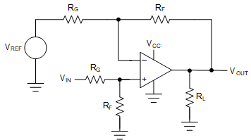
 When the SAC is in noninverting amplifier mode, if the DC component of input signal is small, it is acceptable to amplify both the DC component and AC component. If the input signal contains relatively high DC component while its AC component is small, amplifying the small AC component need high gain but amplifying the DC component with high gain leads to amplifier distortion. Adding biasing on the negative voltage input can address this issue by reducing the common-mode input voltage. Figure 3 shows the typical circuit for single-supply amplifier working in noninverting mode. Similar to the inverting amplifier circuit, the noninverting amplifier can also be implemented using the SAC without external components. The difference is that two SAC modules are needed, because the DAC can be connected only to the positive input of the OA, and the second SAC works in DAC mode to generate the bias voltage to the negative input of the OA. For more details and design considerations for single-supply amplifiers, see the Single-Supply Op Amp Design Techniques application report.
 Figure 3. Single-Supply Noninverting Amplifier