SNVS099I May 1999 – October 2016 LM2991
PRODUCTION DATA.
- 1 Features
- 2 Applications
- 3 Description
- 4 Revision History
- 5 Pin Configuration and Functions
- 6 Specifications
- 7 Detailed Description
- 8 Application and Implementation
- 9 Power Supply Recommendations
- 10Layout
- 11Device and Documentation Support
- 12Mechanical, Packaging, and Orderable Information
封装选项
机械数据 (封装 | 引脚)
散热焊盘机械数据 (封装 | 引脚)
- KTT|5
订购信息
1 Features
- Output Voltage Adjustable from −3 V to −24 V, Typically −2 V to −25 V
- Output Current in Excess of 1 A
- Dropout Voltage Typically 0.6 V at 1-A Load
- Low Quiescent Current
- Internal Short Circuit Current Limit
- Internal Thermal Shutdown With Hysteresis
- TTL, CMOS Compatible ON/OFF Switch
- Functional Complement to the LM2941 Series
2 Applications
- Post Switcher Regulator
- Local, On-Card, Regulation
- Battery Operated Equipment
- Industrial
- Instrumentation
3 Description
The LM2991 is a low dropout adjustable negative regulator with a output voltage range between −3 V to −24 V. The LM2991 provides up to 1 A of load current and features a ON /OFF pin for remote shutdown capability.
The LM2991 uses new circuit design techniques to provide a low dropout voltage, low quiescent current and low temperature coefficient precision reference. The dropout voltage at 1-A load current is typically 0.6 V and an ensured worst-case maximum of 1 V over the entire operating temperature range. The quiescent current is typically 1 mA with a 1-A load current and an input-output voltage differential greater than 3 V. A unique circuit design of the internal bias supply limits the quiescent current to only 9 mA (typical) when the regulator is in the dropout mode (VOUT − VIN ≤ 3 V).
The LM2991 is short-circuit proof, and thermal shutdown includes hysteresis to enhance the reliability of the device when inadvertently overloaded for extended periods. The LM2991 is available in 5-lead TO-220 and DDPAK/TO-263 packages and is rated for operation over the automotive temperature range of −40°C to +125°C. Mil-Aero versions are also available.
Device Information(1)
| PART NUMBER | PACKAGE | BODY SIZE (NOM) |
|---|---|---|
| LM2991 | DDPAK/TO-263 (5) | 10.20 mm × 9.00 mm |
| TO-220 (5) | 14.99 mm × 10.16 mm |
- For all available packages, see the orderable addendum at the end of the data sheet.
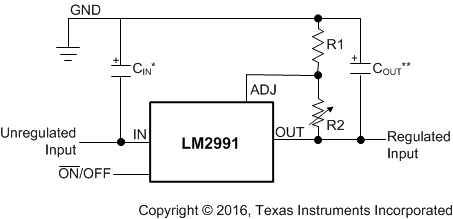
Typical Application
