ZHCSF35A October   2014  – June 2016 PGA300

PRODUCTION DATA.  

  1. 特性
  2. 应用
  3. 说明
  4. 修订历史记录
  5. Pin Configuration and Functions
  6. Specifications
    1. 6.1  Absolute Maximum Ratings
    2. 6.2  ESD Ratings
    3. 6.3  Recommended Operating Conditions
    4. 6.4  Thermal Information
    5. 6.5  Electrical Characteristics - Reverse Voltage Protection
    6. 6.6  Electrical Characteristics - Regulators
    7. 6.7  Electrical Characteristics - Internal Reference
    8. 6.8  Electrical Characteristics - Bridge Sensor Supply
    9. 6.9  Electrical Characteristics - Temperature Sensor Supply
    10. 6.10 Electrical Characteristics - Internal Temperature Sensor
    11. 6.11 Electrical Characteristics - P Gain (Chopper Stabilized)
    12. 6.12 Electrical Characteristics - P Analog-to-Digital Converter
    13. 6.13 Electrical Characteristics - T Gain (Chopper Stabilized)
    14. 6.14 Electrical Characteristics - T Analog-to-Digital Converter
    15. 6.15 Electrical Characteristics - One-Wire Interface
    16. 6.16 Electrical Characteristics - DAC Output
    17. 6.17 Electrical Characteristics - DAC Gain
    18. 6.18 Electrical Characteristics - Non-Volatile Memory
    19. 6.19 Electrical Characteristics - Diagnostics
    20. 6.20 Operating Characteristics
    21. 6.21 Typical Characteristics
  7. Detailed Description
    1. 7.1 Overview
    2. 7.2 Functional Block Diagram
    3. 7.3 Feature Description
      1. 7.3.1  Reverse-Voltage Protection Block
      2. 7.3.2  Linear Regulators
      3. 7.3.3  Internal Reference
        1. 7.3.3.1 High-Voltage Reference
        2. 7.3.3.2 Accurate Reference
      4. 7.3.4  BRG+ to BRG- Supply for the Resistive Bridge
      5. 7.3.5  ITEMP Supply for the Temperature Sensor
      6. 7.3.6  Internal Temperature Sensor
      7. 7.3.7  P Gain
      8. 7.3.8  P Analog-to-Digital Converter
        1. 7.3.8.1 P Sigma-Delta Modulator for P ADC
        2. 7.3.8.2 P Decimation Filter for P ADC
      9. 7.3.9  T Gain
      10. 7.3.10 T Analog-to-Digital Converter
        1. 7.3.10.1 T Sigma-Delta Modulator for T ADC
        2. 7.3.10.2 T Decimation Filters for T ADC
      11. 7.3.11 P GAIN and T GAIN Calibration
      12. 7.3.12 One-Wire Interface (OWI)
        1. 7.3.12.1 Overview of OWI
        2. 7.3.12.2 Activating and Deactivating the OWI Interface
          1. 7.3.12.2.1 Activating OWI Communication
          2. 7.3.12.2.2 Deactivating OWI Communication
        3. 7.3.12.3 OWI Protocol
          1. 7.3.12.3.1 OWI Frame Structure
            1. 7.3.12.3.1.1 Standard Field Structure
            2. 7.3.12.3.1.2 Frame Structure
            3. 7.3.12.3.1.3 Sync Field
            4. 7.3.12.3.1.4 Command Field
            5. 7.3.12.3.1.5 Data Fields
          2. 7.3.12.3.2 OWI Commands
            1. 7.3.12.3.2.1 OWI Write Command
            2. 7.3.12.3.2.2 OWI Read Initialization Command
            3. 7.3.12.3.2.3 OWI Read-Response Command
            4. 7.3.12.3.2.4 OWI Burst-Write Command (EEPROM Cache Access)
            5. 7.3.12.3.2.5 OWI Burst Read Command (EEPROM Cache Access)
          3. 7.3.12.3.3 OWI Operations
            1. 7.3.12.3.3.1 Write Operation
            2. 7.3.12.3.3.2 Read Operation
            3. 7.3.12.3.3.3 EEPROM Burst Write
            4. 7.3.12.3.3.4 EEPROM Burst Read
        4. 7.3.12.4 OWI Communication-Error Status
      13. 7.3.13 DAC Output
        1. 7.3.13.1 Ratiometric vs Absolute
      14. 7.3.14 DAC Gain
      15. 7.3.15 Memory
        1. 7.3.15.1 EEPROM Memory
          1. 7.3.15.1.1 EEPROM Cache
          2. 7.3.15.1.2 EEPROM Programming Procedure
          3. 7.3.15.1.3 EEPROM Programming Current
          4. 7.3.15.1.4 CRC
        2. 7.3.15.2 Control and Status Registers Memory
      16. 7.3.16 Diagnostics
        1. 7.3.16.1 Power Supply Diagnostics
        2. 7.3.16.2 Signal Chain Faults
          1. 7.3.16.2.1 P Gain and T Gain Input Faults
          2. 7.3.16.2.2 P Gain and T Gain Output Diagnostics
          3. 7.3.16.2.3 Masking Signal Chain Faults
          4. 7.3.16.2.4 Fault Detection Timing
      17. 7.3.17 Digital Compensation and Filter
        1. 7.3.17.1 Digital Gain and Offset
        2. 7.3.17.2 TC and NL Correction
          1. 7.3.17.2.1 TC and NL Coefficients
            1. 7.3.17.2.1.1 No TC and NL Coefficients
          2. 7.3.17.2.2 TC Compensation Using the Internal Temperature Sensor
        3. 7.3.17.3 Clamping
        4. 7.3.17.4 Filter
      18. 7.3.18 Filter Coefficients
        1. 7.3.18.1 No Filtering
        2. 7.3.18.2 Filter Coefficients for P ADC Sampling Rate = 128 µs
    4. 7.4 Device Functional Modes
      1. 7.4.1 Voltage Mode
      2. 7.4.2 Current Mode
    5. 7.5 Register Maps
      1. 7.5.1 Register Settings
      2. 7.5.2 Control and Status Registers
        1. 7.5.2.1  DAC_CONFIG
        2. 7.5.2.2  OP_STAGE_CTRL
        3. 7.5.2.3  BRDG_CTRL
        4. 7.5.2.4  P_GAIN_SELECT
        5. 7.5.2.5  T_GAIN_SELECT
        6. 7.5.2.6  TEMP_CTRL
        7. 7.5.2.7  TEMP_SE
        8. 7.5.2.8  DIAG_ENABLE
        9. 7.5.2.9  AFEDIAG_CFG
        10. 7.5.2.10 AFEDIAG_MASK
        11. 7.5.2.11 COMPENSATION_CONTROL
        12. 7.5.2.12 EEPROM_LOCK
        13. 7.5.2.13 EEPROM_PAGE_ADDRESS
        14. 7.5.2.14 EEPROM_CTRL
        15. 7.5.2.15 EEPROM_CRC
        16. 7.5.2.16 EEPROM_STATUS
        17. 7.5.2.17 EEPROM_CRC_STATUS
        18. 7.5.2.18 EEPROM_CRC_VALUE
  8. Application and Implementation
    1. 8.1 Application Information
      1. 8.1.1 4-mA to 20-mA Output With Internal Sense Resistor
        1. 8.1.1.1 Design Requirements
        2. 8.1.1.2 Detailed Design Procedure
          1. 8.1.1.2.1 Calibration Tips
            1. 8.1.1.2.1.1 Programming the EEPROM for 4-mA to 20-mA Output
        3. 8.1.1.3 Application Curve
      2. 8.1.2 0- to 10-V Absolute Output With Internal Drive
        1. 8.1.2.1 Design Requirements
        2. 8.1.2.2 Detailed Design Procedure
          1. 8.1.2.2.1 Programmer Tips
            1. 8.1.2.2.1.1 Resetting the Microprocessor and Enable Digital Interface
            2. 8.1.2.2.1.2 Turning On the Accurate Reference Buffer (REFCAP Voltage)
            3. 8.1.2.2.1.3 Turning On DAC and DAC GAIN
      3. 8.1.3 0- to 5-V Ratiometric Output With Internal Drive
        1. 8.1.3.1 Design Requirements
        2. 8.1.3.2 Detailed Design Procedure
          1. 8.1.3.2.1 Programmer Tips
            1. 8.1.3.2.1.1 Resetting the Microprocessor and Enable Digital Interface
            2. 8.1.3.2.1.2 Turning On the Accurate Reference Buffer (REFCAP Voltage)
            3. 8.1.3.2.1.3 Turning On DAC and DAC GAIN
  9. Power Supply Recommendations
  10. 10Layout
    1. 10.1 Layout Guidelines
    2. 10.2 Layout Example
  11. 11器件和文档支持
    1. 11.1 商标
    2. 11.2 静电放电警告
    3. 11.3 Glossary
  12. 12机械、封装和可订购信息

1 特性

  • 模拟 特性
    • 适用于阻性桥式传感器的模拟前端
    • 传感器灵敏度可调节范围:1mV/V 至 135mV/V
    • 片上温度传感器
    • 可编程增益
    • 适用于信号通道的 16 位 Σ-Δ 模数转换器
    • 适用于温度通道的 16 位 Σ-Δ 模数转换器
    • 14 位输出数模转换器 (DAC)
  • 数字 特性
    • 整个温度范围内的 FSO 精度 < 0.1%
    • 系统响应时间 < 220µs
    • 三阶偏移、增益和非线性温度补偿
    • 诊断功能
    • 集成 EEPROM 用于存储器件操作、校准数据和用户数据
  • 外设 特性
    • 单线接口,可通过电源引脚进行通信,无需额外使用线路
    • 4mA 至 20mA 电流回路接口
    • 比例电压输出和绝对电压输出
    • 电源管理控制
    • 模拟低压检测
  • 通用 特性
    • 工业温度范围:–40°C 至 150°C
    • 电源:
      • 片上电源管理,支持 3.3V 至 30V 的宽电源电压范围
      • 集成反向保护电路

2 应用

  • 压力传感器发送器和换能器
  • 液位计、流量计
  • 阻性现场发送器

3 说明

PGA300 器件提供了一个适用于压阻式和应力计压感元件的接口。该器件具有可编程模拟前端 (AFE)、模数转换器 (ADC) 和数字信号处理功能。这是一套完整的片上系统 (SoC) 解决方案,可直接连接传感元件。此外,PGA300 器件还集成了稳压器和振荡器,最大程度地减少了外部组件数。该器件采用三阶温度和非线性补偿实现高精度。凭借单线制串行接口 (OWI),可以通过电源引脚实现外部通信,从而简化系统校准过程。集成 DAC 支持绝对电压、比例电压以及 4mA 至 20mA 的电流回路输出。

器件信息(1)

器件型号 封装 封装尺寸(标称值)
PGA300 VQFN (36) 6.00mm x 6.00mm
  1. 要了解所有可用封装,请参见数据表末尾的可订购产品附录。

PGA300 简化框图
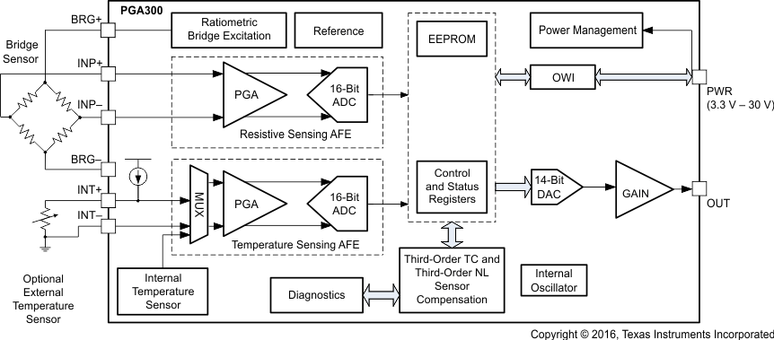
PGA300 fbd_pga300_SLDS204.gif