-
TUSB542 USB Type-CTM 5Gbps 转接驱动器 2:1 多路复用器
- 1
- 1 特性
- 2 应用
- 3 说明
- 4 Pin Configuration and Functions
-
5 Specifications
- 5.1 Absolute Maximum Ratings
- 5.2 ESD Ratings
- 5.3 Recommended Operating Conditions
- 5.4 Thermal Information
- 5.5 Electrical Characteristics, Power Supply Currents
- 5.6 Electrical Characteristics, DC
- 5.7 Electrical Characteristics, Dynamic
- 5.8 Electrical Characteristics, AC
- 5.9 Timing Requirements
- 5.10 Switching Characteristics
- 5.11 Typical Characteristics
- 6 Detailed Description
- 7 Application and Implementation
- 8 Device and Documentation Support
- 9 Revision History
- 10Mechanical, Packaging, and Orderable Information
- 重要声明
Data Sheet
TUSB542 USB Type-CTM 5Gbps 转接驱动器 2:1 多路复用器
本资源的原文使用英文撰写。 为方便起见,TI 提供了译文;由于翻译过程中可能使用了自动化工具,TI 不保证译文的准确性。 为确认准确性,请务必访问 ti.com 参考最新的英文版本(控制文档)。
1 特性
- 可为 USB Type-C™ 端口提供 USB 3.1 Gen-1 5Gbps 超高速 (SS) 2:1 多路复用器
- 支持 USB Type-C 电缆和连接器规范
- 超低功耗架构:
- 工作电流 100mA
- U2/U3 1.3mA
- 无连接 300μA
- 高达 9dB 的可选择均衡、去加重功能和高达 6dB 的输出摆幅
- 集成端接
- RX 检测功能
- 用于电源管理的信号监视
- 无主机或器件端要求 - 支持 USB-C DFP、UFP 或 DRP 端口
- 单电源电压 1.8V ±10%
- 工业温度范围:–40°C 至 85°C
2 应用
- USB 3.1 Gen 1 SS 应用:
3 说明
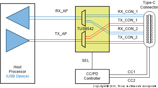
TUSB542 是一款具有 USB Type-C 连接器的双通道 USB 3.1 Gen1
(5Gbps)(也称为 USB-C)转接驱动器支持系统。该器件具有信号调节功能,并且能够为 USB Type-C 可换向连接器转换 USB SS 信号。可以使用外部配置通道逻辑控制器通过 SEL 引脚来控制 TUSB542,以便正确复用信号。
TUSB542 包含接收器均衡和发送器去加重功能,用于在发送和接收数据路径上保持信号的完整性。接收器均衡包含多种增益设置,用以克服插入损耗和码间串扰造成的通道性能退化。为了补偿下行传输线路损耗,输出驱动器还支持去加重配置。此外,自动 LFPS 去加重控制有助于实现完全兼容性。
TUSB542 采用超低功耗架构,由 1.8V 电源供电运行时的功耗非常低。该转接驱动器支持低功耗模式,可进一步降低空闲状态下的功耗。
USB Type-C 转接驱动器采用小型超薄封装,非常适用于许多便携类应用。
(1) 有关详细信息,请参阅节 10
(2) 封装尺寸(长 × 宽)为标称值,并包括引脚(如适用)。
 简化版原理图
 示例应用
示例应用4 Pin Configuration and Functions
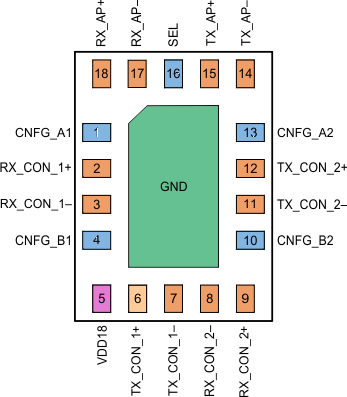
 Figure 4-1 RWQ Package,18-Pin X2QFN(Top View)
Table 4-1 Pin Functions
| PIN | TYPE | DESCRIPTION | |
|---|---|---|---|
| NAME | NO. | ||
| VDD18 | 5 | P | 1.8V Power Supply |
| GND | PAD | G | Reference Ground Thermal Pad. Must connect to GND on the board. |
| SEL | 16 | Input | 2:1 SS MUX control. See Table 1 for signal path
settings.210kΩ internal pullup resistor. H: AP SS signals are connected to Type-C position 1 signals. L: AP SS signals are connected to Type-C position 2 signals |
| CNFG_A1 | 1 | Tri-level Input | Tri-level configuration input pin A1 (for Ch 1): sets channel 1 (AP to redriver) EQ, DE and OS configurations. Pin has integrated pull-up and pull-down resistors of 105kΩ. Refer to Table 6-2 for configuration settings. |
| CNFG_B1 | 4 | Tri-level Input | Tri-level configuration input pin B1 (for Ch 1): sets channel 1 (AP to redriver) EQ, DE and OS configurations. Pin has integrated pull-up and pull-down resistors of 105kΩ. Refer to Table 6-2 for configuration settings. |
| CNFG_A2 | 13 | Tri-level Input | Tri-level configuration input pin A2 (for Ch 2): sets channel 2 (redriver to device) EQ, DE and OS configurations. Pin has integrated pull-up and pull-down resistors of 10 5kΩ. Refer to Table 6-2 for configuration settings. |
| CNFG_B2 | 10 | Tri-level Input | Tri-level configuration input pin B2 (for Ch 2): sets channel 2 (redriver to device) EQ, DE and OS configurations. Pin has integrated pull-up and pull-down resistors of 105kΩ. Refer to Table 6-2 for configuration settings. |
| RX_AP+ | 18 | Diff output | Differential output to Application Processor (AP), 5 Gbps SS positive signal |
| RX_AP- | 17 | Diff output | Differential output to AP, 5Gbps SS negative signal |
| TX_AP+ | 15 | Diff input | Differential input from AP, 5Gbps SS positive signal |
| TX_AP- | 14 | Diff input | Differential input from AP, 5Gbps SS negative signal |
| Rx_Con_1+ | 2 | Diff input | Differential input from Type-C Connector, Position 1, SS positive signal |
| Rx_Con_1- | 3 | Diff input | Differential input from Type-C Connector, Position 1, SS negative signal |
| Tx_Con_1+ | 6 | Diff output | Differential output to Type-C Connector, Position 1, SS positive signal |
| Tx_Con_1- | 7 | Diff output | Differential output to Type-C Connector, Position 1, SS negative signal |
| Rx_Con_2- | 8 | Diff input | Differential input from Type-C Connector, Position 2, SS negative signal |
| Rx_Con_2+ | 9 | Diff input | Differential input from Type-C Connector, Position 2, SS positive signal |
| Tx_Con_2+ | 12 | Diff output | Differential output to Type-C Connector, Position 2, SS positive signal |
| Tx_Con_2- | 11 | Diff output | Differential output to Type-C Connector, Position 2, SS negative signal |