ZHCSEC7A October 2012 – October 2015 TPS92640 , TPS92641
PRODUCTION DATA.
- 1 特性
- 2 应用
- 3 说明
- 4 修订历史记录
- 5 Pin Configuration and Functions
- 6 Specifications
-
7 Detailed Description
- 7.1 Overview
- 7.2 Functional Block Diagram
- 7.3
Feature Description
- 7.3.1 Controlled On-Time Architecture
- 7.3.2 Switching Frequency
- 7.3.3 Average LED Current
- 7.3.4 Analog Dimming and True-Zero Operation
- 7.3.5 Undervoltage Lockout (UVLO)
- 7.3.6 PWM Dimming Using the UDIM Pin
- 7.3.7 External Shunt FET PWM Dimming
- 7.3.8 VCC Regulation and Start-up
- 7.3.9 Precision Reference
- 7.3.10 Control Loop Compensation
- 7.3.11 Overcurrent Protection
- 7.3.12 Overvoltage Protection (OVP)
- 7.3.13 Boot Undervoltage Lockout (UVLO)
- 7.4 Device Functional Modes
-
8 Application and Implementation
- 8.1 Application Information
- 8.2
Typical Applications
- 8.2.1
TPS92640: Design Procedure
- 8.2.1.1 Design Requirements
- 8.2.1.2
Detailed Design Procedure
- 8.2.1.2.1 Set Output Voltage Feedback Ratio
- 8.2.1.2.2 Set Switching Frequency
- 8.2.1.2.3 Set Average LED Current
- 8.2.1.2.4 Set Inductor Ripple Current
- 8.2.1.2.5 Set LED Ripple Current and Determine Output Capacitance, COUT
- 8.2.1.2.6 Choose N-Channel MOSFETs
- 8.2.1.2.7 Choose Input Capacitance
- 8.2.1.2.8 Set the Turnon Voltage and Undervoltage Lockout Hysteresis
- 8.2.2
TPS92640 - PWM Dimming Application
- 8.2.2.1 Design Requirements
- 8.2.2.2
Detailed Design Procedure
- 8.2.2.2.1 Calculate Operating Points
- 8.2.2.2.2 Output Voltage Feedback
- 8.2.2.2.3 Switching Frequency
- 8.2.2.2.4 Set the Feedback Reference and LED Current
- 8.2.2.2.5 Calculate the Inductor Value
- 8.2.2.2.6 Calculate the Output Capacitor Value
- 8.2.2.2.7 Calculate the MOSFET Parameters
- 8.2.2.2.8 Calculate the Minimum Input Capacitance
- 8.2.2.2.9 Undervoltage Lockout and Hysteresis
- 8.2.2.3 Application Curve
- 8.2.1
TPS92640: Design Procedure
- 9 Power Supply Recommendations
- 10Layout
- 11器件和文档支持
- 12机械、封装和可订购信息
1 特性
2 应用
- LED 驱动器/恒流稳压器
- 建筑 LED 照明驱动器
- 汽车类 LED 驱动器
- 通用 LED 照明
3 说明
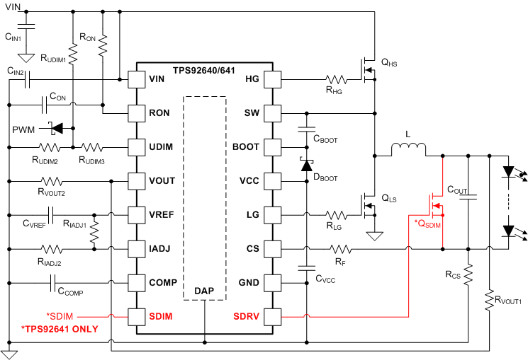
TPS92640 和 TPS92641 器件是用于降压电流稳压器的高电压、同步 N 沟道场效应晶体管 (NFET) 控制器。 输出电流调节基于采用导通时间受控架构的谷值电流模式操作方式。 这种控制方法可简化环路补偿设计,同时使开关频率维持在近似恒定的水平。 TPS92640 和 TPS92641 器件包含一个高电压启动稳压器,该稳压器在 7V 至 85V 的宽输入范围内工作。PWM 控制器专为高速性能而设计,振荡器频率范围高达 1MHz。 高侧和低侧栅极驱动器之间的死区时间进行了优化,以在宽输入工作电压和输出功率范围内高效运行。 TPS92640 和 TPS92641 能够接收模拟和 PWM 输入信号,因此可提供优异的调光控制范围。 输入命令和 LED 电流之间的线性响应特性可通过使用低偏移误差放大器和专用 PWM 调光逻辑实现真正的零 LED 电流的方式实现。 两种器件还具备为低功耗微控制器提供精密基准电流的能力。 保护特性包括:逐周期电流保护、过压保护和热关断。 TPS92641 器件包含一个用于高分辨率 PWM 调光的分流 FET 调光输入和 MOSFET 驱动器。
器件信息(1)
| 部件号 | 封装 | 封装尺寸(标称值) |
|---|---|---|
| TPS92640 | HTSSOP (14) | 4.40mm × 5.00mm |
| TPS92641 | HTSSOP (16) | 4.40mm × 5.00mm |
- 要了解所有可用封装,请见数据表末尾的可订购产品附录。
典型应用图
