Eight Port IO-Link® Master Reference Design
Description
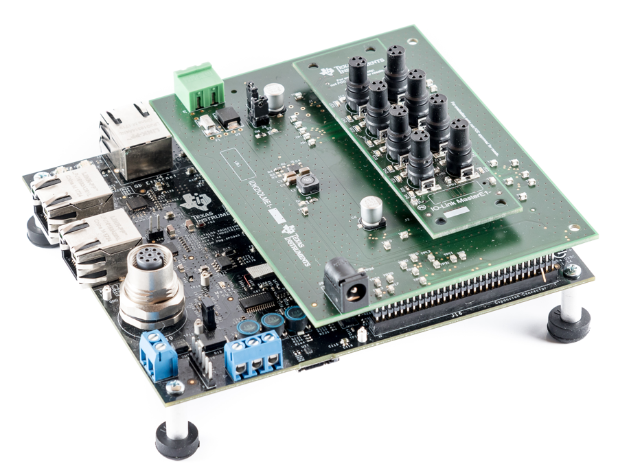
PLC applications requiring fast timing and fast cycle time can now be realized using this reference design which implements an eight-port IO-Link® master. It can be used to build a remote IO gateway to connect to OPC UA, Profinet, EtherCAT, or Ethernet IP. A PRU-based frame handler enables a very flexible way of timing and time synchronization. This design helps build a universal and scalable IO-Link master.
Resources
| TIDA-010016 | Design Folder |
| TIOL111 | Product Folder |
| INA253 | Product Folder |
| TLC59282 | Product Folder |
| LM5165 | Product Folder |
| TPS4H160-Q1 | Product Folder |
Features
- Eight IO-Link ports
- Supports COM1, COM2, COM3
- Supports 400-µs cycle time
- 500-mA current per port
- All ports overcurrent protected and limited
- PRU frame handler enables flexible timing
Applications
- Stand-alone remote IO
- Communication module

1 System Description
Sensors and actuators are the most basic units of automation, feeding information into and acting on instructions from networked systems. Traditionally, these devices connect to control units through interfaces that provide little intelligence, and thus exchange little or no configuration and diagnostic information. Installing a new device requires configuration by hand at the point of use, and without diagnostics it is impossible to perform just-in-time preventive maintenance.
IO-Link (International Electrotechnical Commission [IEC] 61131-9) is an open standards protocol that addresses the need for intelligent control of small devices such as sensors and actuators. This standard provides low-speed point-to-point serial communication between a device and a master that normally serves as a gateway to a fieldbus and PLC. The intelligent link established enables ease of communication for data exchange, configuration, and diagnostics.
An unshielded three-wire cable as long as 20 meters, normally equipped with M12 connectors, establishes an IO-Link connection. Data rates range up to 230 kbps with a nonsynchronous minimum cycle time of 400 µs, +10%. Four operating modes support bidirectional input/output (I/O), digital input, digital output and deactivation. Security mechanisms and deterministic data delivery are not specified. A profile known as the IO Device Description (IODD) contains communication properties; device parameters; identification, process and diagnostic data; and information specifically about the device and manufacturer.
The many advantages of an IO-Link system include standardized wiring, increased data availability, remote monitoring and configuration, simple replacement of devices and advanced diagnostics. IO-Link permits factory managers to receive sensor updates and plan for upcoming maintenance or replacement. Swapping out a sensing or actuation unit that needs replacement and configuring a new one from the PLC through the IO-Link master eliminates manual setup and reduces downtime. Switching production remotely from one configuration to another without visiting the factory floor facilitates easier product customization. Factories can upgrade production lines readily to IO-Link, since it is backwards-compatible with existing standard I/O installations and cabling. Altogether, these capabilities result in reduced overall costs, more efficient processes, and greater machine availability.
1.1 Key System Specifications
| PARAMETER | SPECIFICATIONS | DETAILS |
|---|---|---|
| Input voltage | External 24-V power supply | Section 2.3.4 |
| Input current | Depending on connected load (5 A recommended) | Section 2.3.4 |
| Output voltage | 24 V | Section 2.3.3 |
| Output current per port | 500 mA | Section 2.3.3 |
| Total output current | 4 A | Section 2.3.3 |
| Number of IO-Link master ports | 8 | |
| Number of Ethernet ports | 2 | |
| Supported IO-Link data rates | COM1, COM2, COM3 | |
| Supported IO-Link cycle time | 400 µs | |
| Frame handler | Section 2.4.1 | |
| Oversampling factor | 8 times | |
| Sampling frequency | Up to 1.8432 MSPS per channel (COM3) | |
| Supported IO-Link transmission rates | COM3, COM2, COM1 | |
| Equivalent Baud-rate | 230.4 kbaud, 38.4 kbaud, 4.8 kbaud | |
| RX buffer size | 128 bytes | |
| TX buffer size | 2 x 128 bytes (double send buffer) | |
| Start bit and bit filter | Based on look-up table (can be adjusted) | |
| Parity check | Supported | |
| T1 time (UART frame transmission delay, master) | 0 Tbit | |
| T2 time check (UART frame transmission delay, device) | Supported, hard coded to 5 | |
| Ta time check (maximum response time) | Supported and user adjustable by register |