SWRA602 October 2018 CC1310 , CC1350
TI Tech Note
The new TI wM-Bus Stack release Rev2.0.0 for CC1310 and CC1350 single-chip Wireless MCUs upgrades the feature set from OMSv3.0.1 to OMSv4.1.2, which is the latest public release by the OMS Group. The ultra-low-power consumption modes supported by this Stack take full advantage of the advanced power saving features of the CC1310 and CC1350 devices, as described later. For a 3.6 V supply the transmit current is typically about 13.4 mA at +10 dBm, while receive current is 5.4 mA at maximum RX sensitivity. During wM-Bus inactivity periods, which can extend from a few seconds to several hours, CC1310 and CC1350 are operating in either Standby (0.8 µA) or Shutdown mode (0.2 µA) to minimize power consumption.
The CC1310 and CC1350 Wireless MCUs execute the wM-Bus stack with up to 70% less power consumption than the two chip MSP430 + CC1125 solution, while maintaining the market leading sensitivity and T-mode compatibility of CC1125. The CC13x0 sensitivity at 1% BER for T-mode (conducted measurement) is -105.0 dBm and supports the ±12% data rate variation tolerance specification in T-mode. In C-mode, with a very narrow data rate variation limit of ± 100 ppm, the sensitivity improves to -106.3 dBm.
TI's new OMSV4.1.2 wM-Bus Stack supports the popular S-, T-, or C-modes, as described in the EN13757-4:2014-2 standard and offers binary images for either Meters or Data Collector devices in all these modes. Data Collector images in the TI stack are always bidirectional, whereas Meter images can be also unidirectional; denoted by the number 2 or 1.
Ultra-low power consumption of the wM‑Bus subsystem is very important for any battery operated devices, such as water, heat, or gas meters and heat-cost allocators. E-meters, being always powered, also benefit from lower average power consumption, as the energy for the SRD wireless communication must be paid by the utility or the end users.
Different frequencies and coding schemes at the physical (PHY) layer demand a special firmware image (or patch) for the software defined core of CC13x0 with optimized RF settings for each wM‑Bus PHY mode. For supporting the combined T- and C-mode reception at the "Other" device (such as Data Collector or a Handheld Reader) the T-/C-mode patch has to be used. It offers the advantage to detect "on the fly" if the incoming data packet is in T- or C-mode and based on this decode the "3-of-6" coding in T-mode or leave the data "as is" in C-mode. The combination with the S-mode patch is implemented in the T2 and C2-mode Data Collector binaries, sending S-mode packets back to the T2-mode Meter devices.
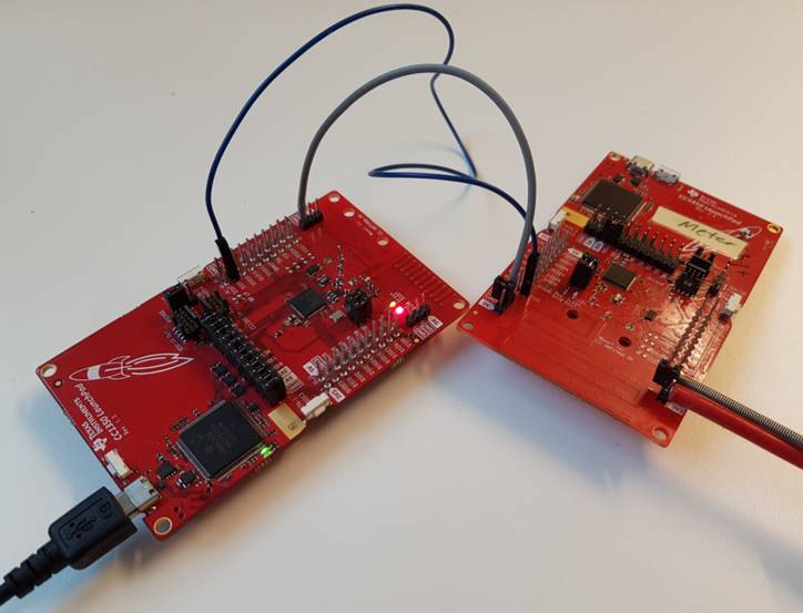
 Figure 1. Left CC1350LP as a Host MCU, CC1350LP to the Right is the wM‑Bus "Meter" DUT
 Ultra-low power modes of CC1310 and CC1350
The low-power modes inside the Meter devices should be both internally and externally manageable to accommodate various wM-Bus stack operational scenarios. If an external Host MCU is present, it should be able to control the modes of the RF subsystem, which using the integrated TI RTOS power management autonomously will go to lowest power state, depending on wM‑Bus Stack timings and scheduled transmit or receive activity. The two ultra-low power modes in the latest TI wM-Bus Stack Revision use the Shutdown and Standby features of CC1310 and CC1350. In shutdown mode the CC13x0 device draws merely 91 nA but all hardware blocks of the device are disabled and the RAM content is lost, such that only Wakeup on external events like pin toggling are possible. This means the wM‑Bus Stack must restart using the default Stack values after exiting from Shutdown mode. If specific parameters have to keep their previous value (such as the Access Number of a wM‑Bus packet, which according to OMSv4.1.2 needs to be incremented continuously with every synchronous transmission) then these parameters must be stored prior to entering Shutdown mode and afterwards restored by the Host MCU.
 Figure 2. Low-Power Mode Activated by the TI_SLEEP_PIN
 If RTC, CPU, RAM, and (partial) register retention is preferred, then the CC13x0 Standby mode is the suitable solution with merely 0.8 µA at 25°C drawn. This average current will increase to just 1.2 µA at 60°C and 2.5 µA at 85°C, which is significantly better (lower) than comparable solutions and an excellent fit for all applications with regular or higher than average ambient temperature profile, such as Heat meters or Heat Cost Allocators.
Ultra-low power modes in wM-Bus Stack
The TI OMsv4.1.2 Stack utilizes the SDK 2.20.00.38 package for CC13x0 and requires two additional pins: TI_SYNC_PIN and TI_SLEEP_PIN; theirs exact DIO numbers are user configurable. Communication with the external Host MCU runs over UART, where DIO2 is the UART_RX and DIO3 is the UART_TX pin.
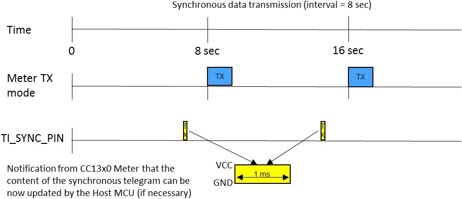
 Figure 3. Updating Periodic Synchronous Meter Telegrams (StandBy Mode Enabled)
 Standby mode is the default but can be changed to Shutdown by sending a dedicated serial command over UART. TI_SLEEP_PIN is driven by the Host MCU and signals to the CC13x0 to go into Low Power. This DIO pin, configured as NOPULL, must be held HIGH during Active mode (transmit or receive) and pulled LOW (=GND) for enabling low-power mode.
CC13x0 toggles the TI_SYNC_PIN automatically two seconds prior to the next periodic transmision for 1 ms and enables the update of the synchronous wM-Bus telegrams content. The Host MCU can now pass to over UART the new wM-Bus data (if any).
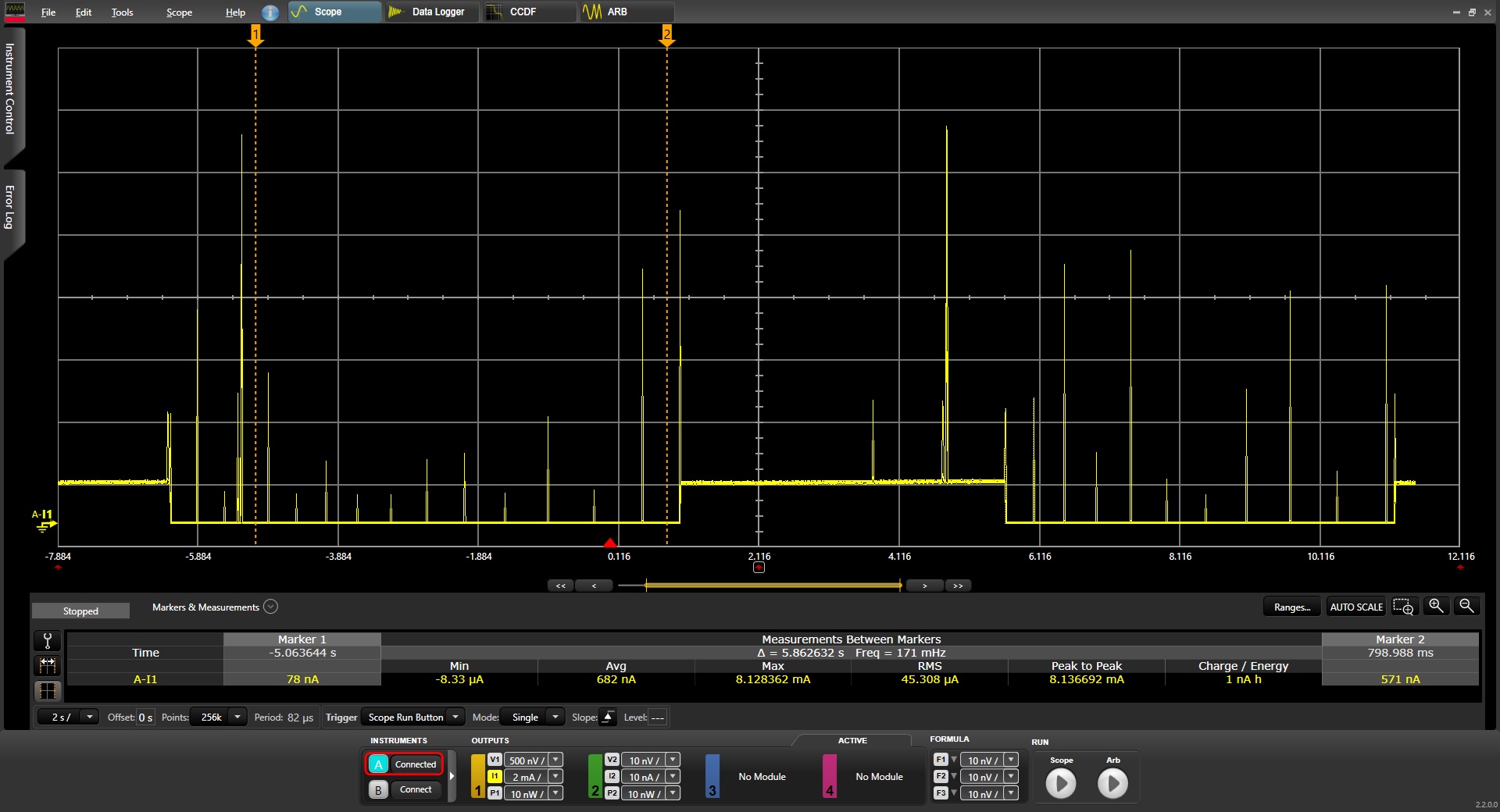
For testing two CC1350 LaunchPad™ development kits were wired as in Figure 1: one CC1350LP is used as the Host MCU, while the second CC1350LP is programmed with the "Serial_cc13xx_Meter_C1_T1" binary image from TI wM‑Bus Stack Rev2.0.0. The wM‑Bus Stack code, using Button 1 of the CC1350 LaunchPad by default, was modified to IOID1 for the signal level control of the power down modes by a Host MCU. The CC1350 Wireless MCUs then consumes 91 nA in average, which was measured with a Agilent N6781A box. The CC1350 in Standby mode draws 682 nA (Figure 4) at 3.3-V supply, matching the 0.8 µA data sheet value.
 Figure 4. Average CC1350 Standby Current of 682 nA at 3.3 V With Recharge Pulses over 5.8 s
 Summary
TI’s latest wM-Bus OMSv4.1.2 compatible Rev.2.0.0 Stack implements the Standby and Shutdown power-down modes as per CC13x0 datasheets for any supported Meter device configuration. An external Host MCU controls the mode selection using a dedicated Serial command and toggling the DIO pin level to enable Standby or Shutdown mode, see Stack documentation for details. In Standby mode the wM-Bus Stack keeps its state while after Shutdown mode the Host MCU will need to restart the wM‑Bus Stack and restore any previously saved values, such as the Access Number field.